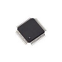
SAF-XC886CLM-8FFI 5V AC Infineon Technologies, SAF-XC886CLM-8FFI 5V AC Datasheet - Page 92

SAF-XC886CLM-8FFI 5V AC
Manufacturer Part Number
SAF-XC886CLM-8FFI 5V AC
Description
IC MCU 8BIT FLASH TQFP-48
Manufacturer
Infineon Technologies
Series
XC8xxr
Datasheet
1.SAF-XC888CLM-6FFA_5V_AC.pdf
(144 pages)
Specifications of SAF-XC886CLM-8FFI 5V AC
Program Memory Type
FLASH
Program Memory Size
32KB (32K x 8)
Package / Case
48-TFQFP
Core Processor
XC800
Core Size
8-Bit
Speed
103.2MHz
Connectivity
CAN, LIN, SSI, UART/USART
Peripherals
Brown-out Detect/Reset, POR, PWM, WDT
Number Of I /o
34
Ram Size
1.75K x 8
Voltage - Supply (vcc/vdd)
4.5 V ~ 5.5 V
Data Converters
A/D 8x10b
Oscillator Type
Internal
Operating Temperature
-40°C ~ 85°C
Data Bus Width
8 bit
Data Ram Size
1.75 KB
Interface Type
JTAG/SPI/SSC/UART
Maximum Clock Frequency
24 MHz
Number Of Programmable I/os
48
Number Of Timers
4
Operating Supply Voltage
5 V
Maximum Operating Temperature
+ 85 C
Mounting Style
SMD/SMT
Minimum Operating Temperature
- 40 C
On-chip Adc
8-ch x 10-bit
Lead Free Status / RoHS Status
Contains lead / RoHS non-compliant
For Use With
MCBXC88X - BOARD EVAL FOR INFINEON XC88X
Eeprom Size
-
Lead Free Status / Rohs Status
Lead free / RoHS Compliant
Other names
FX886CLM8FFI5VACXT
SAF-XC886CLM-8FFI AB
SAF-XC886CLM-8FFI AB
SAFXC886CLM8FFIABT
SP000217341
SAF-XC886CLM-8FFI AB
SAF-XC886CLM-8FFI AB
SAFXC886CLM8FFIABT
SP000217341
3.13
The XC886/888 provides two Universal Asynchronous Receiver/Transmitter (UART and
UART1) modules for full-duplex asynchronous reception/transmission. Both are also
receive-buffered, i.e., they can commence reception of a second byte before a
previously received byte has been read from the receive register. However, if the first
byte still has not been read by the time reception of the second byte is complete, one of
the bytes will be lost.
Features
•
•
•
•
The UART modules can operate in the four modes shown in
Table 29
Operating Mode
Mode 0: 8-bit shift register
Mode 1: 8-bit shift UART
Mode 2: 9-bit shift UART
Mode 3: 9-bit shift UART
1) For UART1 module, the baud rate is fixed at f
There are several ways to generate the baud rate clock for the serial port, depending on
the mode in which it is operating. In mode 0, the baud rate for the transfer is fixed at
f
and can be configured to either
available. The variable baud rate is set by the underflow rate on the dedicated baud-rate
generator. For UART module, the variable baud rate alternatively can be set by the
overflow rate on Timer 1.
3.13.1
Both UART modules have their own dedicated baud-rate generator, which is based on
a programmable 8-bit reload value, and includes divider stages (i.e., prescaler and
Data Sheet
PCLK
– Interrupt enabling and corresponding flag
Full-duplex asynchronous modes
– 8-bit or 9-bit data frames, LSB first
– Fixed or variable baud rate
Receive buffered
Multiprocessor communication
Interrupt generation on the completion of a data transmission or reception
/2. In mode 2, the baud rate is generated internally based on the UART input clock
UART and UART1
Baud-Rate Generator
UART Modes
f
PCLK
/32 or
PCLK
/64.
Baud Rate
f
Variable
f
Variable
f
PCLK
PCLK
85
PCLK
/2
/32 or
/64. For UART1 module, only
f
PCLK
/64
Table
1)
Functional Description
29.
XC886/888CLM
V1.2, 2009-07
f
PCLK
/64 is


