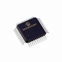
PIC16LC774/PQ Microchip Technology, PIC16LC774/PQ Datasheet - Page 128

PIC16LC774/PQ
Manufacturer Part Number
PIC16LC774/PQ
Description
IC MCU OTP 4KX14 A/D PWM 44-MQFP
Manufacturer
Microchip Technology
Series
PIC® 16Cr
Specifications of PIC16LC774/PQ
Core Processor
PIC
Core Size
8-Bit
Speed
20MHz
Connectivity
I²C, SPI, UART/USART
Peripherals
Brown-out Detect/Reset, POR, PWM, WDT
Number Of I /o
33
Program Memory Size
7KB (4K x 14)
Program Memory Type
OTP
Ram Size
256 x 8
Voltage - Supply (vcc/vdd)
2.5 V ~ 5.5 V
Data Converters
A/D 10x12b
Oscillator Type
External
Operating Temperature
0°C ~ 70°C
Package / Case
44-MQFP, 44-PQFP
Processor Series
PIC16LC
Core
PIC
Data Bus Width
8 bit
Data Ram Size
256 B
Interface Type
I2C, SPI, SSP, UART
Maximum Clock Frequency
20 MHz
Number Of Programmable I/os
33
Number Of Timers
3 bit
Operating Supply Voltage
2.5 V to 5.5 V
Maximum Operating Temperature
+ 70 C
Mounting Style
SMD/SMT
3rd Party Development Tools
52715-96, 52716-328, 52717-734
Development Tools By Supplier
ICE2000, DM163022
Minimum Operating Temperature
0 C
On-chip Adc
10 bit
Lead Free Status / RoHS Status
Lead free / RoHS Compliant
Eeprom Size
-
Lead Free Status / Rohs Status
Details
Available stocks
Company
Part Number
Manufacturer
Quantity
Price
Company:
Part Number:
PIC16LC774/PQ
Manufacturer:
Microchip Technology
Quantity:
10 000
- Current page: 128 of 201
- Download datasheet (3Mb)
PIC16C77X
FIGURE 12-1: CONFIGURATION WORD
12.2
12.2.1
The PIC16C77X can be operated in four different oscil-
lator modes. The user can program two configuration
bits (FOSC1 and FOSC0) to select one of these four
modes:
• LP
• XT
• HS
• RC
DS30275A-page 128
bit13
bit 13-12: CP1:CP0: Code Protection bits
bit 9-8:
bit 5-4:
bit 11-10: BORV1:BORV0: Brown-out Reset Voltage bits
bit 7:
bit 6:
bit 3:
bit 2:
bit 1-0:
Note 1: Enabling Brown-out Reset automatically enables the Power-up Timer (PWRT) regardless of the value of bit PWRTE.
CP1
2: All of the CP1:CP0 pairs have to be given the same value to enable the code protection scheme listed.
3: These are the minimum trip points for the BOR, see Table 15-4 for the trip point tolerances. Selection of an unused
CP0 BORV1 BORV0 CP1
12
Oscillator Configurations
OSCILLATOR TYPES
11 = Program memory code protection off
10 = 0800h-0FFFh code protected
01 = 0400h-0FFFh code protected
00 = 0000h-0FFFh code protected
11 = V
10 = V
01 = V
00 = V
Unimplemented, Read as ’1’
BODEN: Brown-out Reset Enable bit
1 = Brown-out Reset enabled
0 = Brown-out Reset disabled
PWRTE: Power-up Timer Enable bit
1 = PWRT disabled
0 = PWRT enabled
WDTE: Watchdog Timer Enable bit
1 = WDT enabled
0 = WDT disabled
FOSC1:FOSC0: Oscillator Selection bits
11 = RC oscillator
10 = HS oscillator
01 = XT oscillator
00 = LP oscillator
Ensure the Power-up Timer is enabled anytime Brown-out Reset is enabled.
setting may result in an inadvertant interrupt.
Low Power Crystal
Crystal/Resonator
High Speed Crystal/Resonator
Resistor/Capacitor
11
BOR
BOR
BOR
BOR
set to 2.5V
set to 2.7V
set to 4.2V
set to 4.5V
10
9
CP0
8
7
-
(2)
(1)
(1)
BODEN CP1
Advance Information
6
(3)
5
CP0 PWRTE
4
12.2.2
In XT, LP or HS modes, a crystal or ceramic resonator
is connected to the OSC1/CLKIN and OSC2/CLKOUT
pins to
PIC16C77X oscillator design requires the use of a par-
allel cut crystal. Use of a series cut crystal may give a
frequency out of the crystal manufacturers specifica-
tions.
A difference from the other mid-range devices may be
noted in that the device can be driven from an external
clock only when configured in HS mode
3
WDTE
CRYSTAL OSCILLATOR/CERAMIC
RESONATORS
2
establish
FOSC1
1
oscillation
FOSC0
1999 Microchip Technology Inc.
bit0
Register:
Address
(Figure
(Figure
CONFIG
12-2).
2007h
12-3).
The
Related parts for PIC16LC774/PQ
Image
Part Number
Description
Manufacturer
Datasheet
Request
R

Part Number:
Description:
3.5KB Flash, 128B RAM, 18 I/O, CLC, CWG, DDS, 10-bit ADC 20 QFN 4x4mm TUBE
Manufacturer:
Microchip Technology
Datasheet:

Part Number:
Description:
3.5KB Flash, 128B RAM, 18 I/O, CLC, CWG, DDS, 10-bit ADC 20 PDIP .300in TUBE
Manufacturer:
Microchip Technology
Datasheet:

Part Number:
Description:
3.5KB Flash, 128B RAM, 18 I/O, CLC, CWG, DDS, 10-bit ADC 20 SOIC .300in TUBE
Manufacturer:
Microchip Technology
Datasheet:

Part Number:
Description:
3.5KB Flash, 128B RAM, 18 I/O, CLC, CWG, DDS, 10-bit ADC 20 SSOP .209in TUBE
Manufacturer:
Microchip Technology
Datasheet:

Part Number:
Description:
3.5KB Flash, 128B RAM, 18 I/O, CLC, CWG, DDS, 10-bit ADC 20 QFN 4x4mm TUBE
Manufacturer:
Microchip Technology
Datasheet:

Part Number:
Description:
3.5KB Flash, 128B RAM, 18 I/O, CLC, CWG, DDS, 10-bit ADC 20 PDIP .300in TUBE
Manufacturer:
Microchip Technology
Datasheet:

Part Number:
Description:
3.5KB Flash, 128B RAM, 18 I/O, CLC, CWG, DDS, 10-bit ADC 20 SOIC .300in TUBE
Manufacturer:
Microchip Technology
Datasheet:

Part Number:
Description:
3.5KB Flash, 128B RAM, 18 I/O, CLC, CWG, DDS, 10-bit ADC 20 SSOP .209in TUBE
Manufacturer:
Microchip Technology
Datasheet:

Part Number:
Description:
3.5KB Flash, 128B RAM, 18 I/O, CLC, CWG, DDS, 10-bit ADC 20 QFN 4x4mm T/R
Manufacturer:
Microchip Technology
Datasheet:

Part Number:
Description:
3.5KB Flash, 128B RAM, 18 I/O, CLC, CWG, DDS, 10-bit ADC 20 SOIC .300in T/R
Manufacturer:
Microchip Technology
Datasheet:

Part Number:
Description:
3.5KB Flash, 128B RAM, 18 I/O, CLC, CWG, DDS, 10-bit ADC 20 SSOP .209in T/R
Manufacturer:
Microchip Technology
Datasheet:

Part Number:
Description:
3.5KB Flash, 128B RAM, 18 I/O, CLC, CWG, DDS, 10-bit ADC 20 QFN 4x4mm TUBE
Manufacturer:
Microchip Technology
Datasheet:

Part Number:
Description:
3.5KB Flash, 128B RAM, 18 I/O, CLC, CWG, DDS, 10-bit ADC 20 PDIP .300in TUBE
Manufacturer:
Microchip Technology
Datasheet:

Part Number:
Description:
3.5KB Flash, 128B RAM, 18 I/O, CLC, CWG, DDS, 10-bit ADC 20 SOIC .300in TUBE
Manufacturer:
Microchip Technology
Datasheet:

Part Number:
Description:
3.5KB Flash, 128B RAM, 18 I/O, CLC, CWG, DDS, 10-bit ADC 20 SSOP .209in TUBE
Manufacturer:
Microchip Technology
Datasheet:


