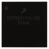
DSP56311VL150 Freescale Semiconductor, DSP56311VL150 Datasheet - Page 5

DSP56311VL150
Manufacturer Part Number
DSP56311VL150
Description
IC DSP 24BIT FIXED POINT 196-BGA
Manufacturer
Freescale Semiconductor
Series
DSP563xxr
Type
Fixed Pointr
Datasheet
1.DSP56311VL150R2.pdf
(96 pages)
Specifications of DSP56311VL150
Interface
Host Interface, SSI, SCI
Clock Rate
150MHz
Non-volatile Memory
ROM (576 B)
On-chip Ram
384kB
Voltage - I/o
3.30V
Voltage - Core
1.80V
Operating Temperature
-40°C ~ 100°C
Mounting Type
Surface Mount
Package / Case
196-MAPBGA
Package
196MA-BGA
Numeric And Arithmetic Format
Fixed-Point
Maximum Speed
150 MHz
Ram Size
384 KB
Device Million Instructions Per Second
150 MIPS
Lead Free Status / RoHS Status
Lead free / RoHS Compliant
Available stocks
Company
Part Number
Manufacturer
Quantity
Price
Company:
Part Number:
DSP56311VL150
Manufacturer:
FREESCALE
Quantity:
201
Company:
Part Number:
DSP56311VL150
Manufacturer:
MOTOLOLA
Quantity:
1 045
Company:
Part Number:
DSP56311VL150
Manufacturer:
Freescale Semiconductor
Quantity:
10 000
Part Number:
DSP56311VL150
Manufacturer:
FREESCALE
Quantity:
20 000
Company:
Part Number:
DSP56311VL150B1
Manufacturer:
ST
Quantity:
101
Company:
Part Number:
DSP56311VL150B1
Manufacturer:
Freescale Semiconductor
Quantity:
10 000
Company:
Part Number:
DSP56311VL150R2
Manufacturer:
Freescale Semiconductor
Quantity:
10 000
Signals/Connections
The DSP56311 input and output signals are organized into functional groups as shown in Table 1-1. Figure 1-1
diagrams the DSP56311 signals by functional group. The remainder of this chapter describes the signal pins in
each functional group.
Note:
Freescale Semiconductor
Power (V
Ground (GND)
Clock
PLL
Address bus
Data bus
Bus control
Interrupt and mode control
Host interface (HI08)
Enhanced synchronous serial interface (ESSI)
Serial communication interface (SCI)
Timer
OnCE/JTAG Port
Notes:
The Clock Output (
are supported by the DSP56311 at operating frequencies up to 100 MHz. Therefore, above 100 MHz, you must
enable bus arbitration by setting the Asynchronous Bus Arbitration Enable Bit (ABE) in the operating mode register.
When set, the ABE bit eliminates the required set-up and hold times for
addition, DRAM access is not supported above 100 MHz.
CC
1.
2.
3.
4.
5.
)
Port A signals define the external memory interface port, including the external address bus, data bus, and control signals.
Port B signals are the HI08 port signals multiplexed with the GPIO signals.
Port C and D signals are the two ESSI port signals multiplexed with the GPIO signals.
Port E signals are the SCI port signals multiplexed with the GPIO signals.
There are 5 signal connections that are not used. These are designated as no connect (NC) in the package description (see
Chapter 3).
CLKOUT
Table 1-1.
),
BCLK
Functional Group
,
DSP56311 Technical Data, Rev. 8
BCLK
DSP56311 Functional Signal Groupings
,
CAS
, and
RAS[0–3]
signals used by other DSP56300 family members
BB
and
BG
Ports C and D
with respect to
Port A
Port B
Port E
1
2
4
3
CLKOUT
Number of
Signals
20
66
18
24
13
16
12
2
3
5
3
3
6
. In
1
1-1


