TWR-MCF51MM Freescale Semiconductor, TWR-MCF51MM Datasheet - Page 25
TWR-MCF51MM
Manufacturer Part Number
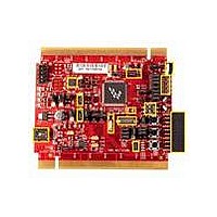
TWR-MCF51MM
Description
TOWER SYSTEM BOARD MCF51MM
Manufacturer
Freescale Semiconductor
Series
ColdFire®, Flexis™r
Type
MCUr
Specifications of TWR-MCF51MM
Contents
Board, 3 Modules, MED-EKG Kit, Cables, Documentation, DVD
Product
Microcontroller Modules
Data Bus Width
32 bit
Core Processor
MCF51MM
Clock Speed
32 KHz
Interface Type
RS232, RS485, CAN , USB
Flash
256 KB
Operating Supply Voltage
3.3 V
Silicon Manufacturer
Freescale
Core Architecture
Coldfire
Core Sub-architecture
Coldfire V1
Silicon Core Number
MCF51
Silicon Family Name
Flexis - MCF51MM
Rohs Compliant
Yes
For Use With/related Products
Freescale Tower System, MCF51MM
Lead Free Status / RoHS Status
Lead free / RoHS Compliant


Freescale Semiconductor
Freescale reserves the right to change the detail specifications as may be required to permit improvements in the design of its products.
1
2
3
4
#
8
Data in Typical column was characterized at 3.0 V, 25°C or is typical recommended value.
ON = System Clock Gating Control registers turn on system clock to the corresponding modules.
OFF = System Clock Gating Control registers turn off system clock to the corresponding modules.
All digital pins must be configured to a known state to prevent floating pins from adding current. Smaller packages may have some
pins that are not bonded out; however, software must still be configured to the largest pin package available so that all pins are in
a known state. Otherwise, floating pins that are not bonded in the smaller packages may result in a higher current draw.
NOTE: I/O pins are configured to output low, input-only pins are configured to pullup enabled. IRO pin connects to ground. FB_AD12
pin is pullup enabled. TRIAMPx, OPAMPx, DACO, and VREFO pins are at reset state and unconnected.
#
1
2
3
4
5
6
7
Symbol
LPO
EREFSTEN
IREFSTEN
TOD
LVD
PRACMP
ADC
S3I
Parameter
DD
1
1
1
Stop3 mode
supply
current
1
RANGE = HGO = 0
Does not include clock source
current
LVDSE = 1
Not using the bandgap
(BGBE = 0)
ADLPC = ADLSMP = 1
Not using the bandgap
(BGBE = 0)
Parameter
4
Table 10. Supply Current Characteristics (continued)
No clocks active
Condition
Table 11. Typical Stop Mode Adders
—
—
Freq
Bus
N/A
N/A
N/A
N/A
N/A
N/A
N/A
N/A
V
DD
–40
600
116
190
50
50
17
—
3
3
3
3
2
2
2
2
(V)
650
117
195
25
75
73
75
18
0.650
0.400
Temperature (°C)
Typ
8.5
8.2
20
53
18
47
1
750
100
126
210
100
70
80
24
0.900
Max
1.0
18
28
63
16
26
59
150
850
150
132
220
85
93
35
Unit
µA
µA
µA
µA
µA
µA
µA
µA
Electrical Characteristics
1000
105
250
125
250
172
260
74
–40 to
–40 to
Temp
(C)
105
105
25
70
85
25
70
85
Units
nA
nA
µA
nA
µA
µA
µA
C
C
C
C
C
C
C
P
P
C
D
D
D
T
T
T
T
25
Related parts for TWR-MCF51MM
Image
Part Number
Description
Manufacturer
Datasheet
Request
R

Part Number:
Description:
Power Management IC Development Tools Low-volt 3-phase MC
Manufacturer:
Freescale Semiconductor
Datasheet:
Part Number:
Description:
K53N512CMD100 TWR Module
Manufacturer:
Freescale Semiconductor
Datasheet:
Part Number:
Description:
TWR-K53N512 Dev Kit
Manufacturer:
Freescale Semiconductor
Datasheet:

Part Number:
Description:
CONV DC/DC TRI OUT 5,15,-15V
Manufacturer:
Murata Power Solutions Inc
Datasheet:

Part Number:
Description:
CONV DC/DC TRI OUT 5,12,-12V
Manufacturer:
Murata Power Solutions Inc
Datasheet:

Part Number:
Description:
CONV DC/DC TRI OUT 5,15,-15V
Manufacturer:
Murata Power Solutions Inc
Datasheet:

Part Number:
Description:
LCD MODULE FOR TWR SYSTEM
Manufacturer:
Freescale Semiconductor
Datasheet:

Part Number:
Description:
DC/DC TH 11W 5-5/12V Triple A
Manufacturer:
Murata Power Solutions Inc
Datasheet:


Part Number:
Description:
TOWER SYSTEM PROTO
Manufacturer:
Freescale Semiconductor
Datasheet:

Part Number:
Description:
TOWER ELEVATOR BOARDS HARDWARE
Manufacturer:
Freescale Semiconductor
Datasheet:

Part Number:
Description:
TOWER SERIAL I/O HARDWARE
Manufacturer:
Freescale Semiconductor
Datasheet:

Part Number:
Description:
TOWER SYSTEM BOARD MPC5125
Manufacturer:
Freescale Semiconductor
Datasheet: