TWR-MCF51MM Freescale Semiconductor, TWR-MCF51MM Datasheet - Page 39
TWR-MCF51MM
Manufacturer Part Number
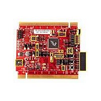
TWR-MCF51MM
Description
TOWER SYSTEM BOARD MCF51MM
Manufacturer
Freescale Semiconductor
Series
ColdFire®, Flexis™r
Type
MCUr
Specifications of TWR-MCF51MM
Contents
Board, 3 Modules, MED-EKG Kit, Cables, Documentation, DVD
Product
Microcontroller Modules
Data Bus Width
32 bit
Core Processor
MCF51MM
Clock Speed
32 KHz
Interface Type
RS232, RS485, CAN , USB
Flash
256 KB
Operating Supply Voltage
3.3 V
Silicon Manufacturer
Freescale
Core Architecture
Coldfire
Core Sub-architecture
Coldfire V1
Silicon Core Number
MCF51
Silicon Family Name
Flexis - MCF51MM
Rohs Compliant
Yes
For Use With/related Products
Freescale Tower System, MCF51MM
Lead Free Status / RoHS Status
Lead free / RoHS Compliant


1
2
3
4
5
3.11
A multi-function external bus interface called Mini-FlexBus is provided with basic functionality to
interface to slave-only devices up to a maximum bus frequency of
to asynchronous or synchronous devices such as external boot ROMs, flash memories, gate-array logic, or
other simple target (slave) devices with little or no additional circuitry. For asynchronous devices a simple
chip-select based interface can be used.
All processor bus timings are synchronous; that is, input setup/hold and output delay are given in respect
to the rising edge of a reference clock, MB_CLK. The MB_CLK frequency is half the internal system bus
frequency.
The following timing numbers indicate when data is latched or driven onto the external bus, relative to the
Mini-FlexBus output clock (MB_CLK). All other timing relationships can be derived from these values.
Freescale Semiconductor
#
6
Data in Typical column was characterized at 3.0 V, 25C or is typical recommended value.
When MCG is configured for FEE or FBE mode, input clock source must be divisible using RDIV to within the range of 31.25 kHz to 39.0625 kHz.
When MCG is configured for PEE or PBE mode, input clock source must be divisible using RDIV to within the range of 1 MHz to 2 MHz.
This parameter is characterized and not tested on each device. Proper PC board layout porcedures must be followed to achieve specifications.
4 MHz crystal.
o
Freescale reserves the right to change the detail specifications as may be required to permit improvements in the design of its products.
Crystal start-up time
Mini-FlexBus Timing Specifications
Table 19. XOSC (Temperature Range = –40 to 105
4
Characteristic
C
• Low range, low gain (RANGE =
• Low range, high gain
• High range, low gain
• High range, high gain
1
0, HGO = 0)
(RANGE = 0, HGO = 1)
(RANGE = 1, HGO = 0)
(RANGE = 1, HGO = 1)
EXTAL
Crystal or Resonator
MCU
R
F
5
5
t
t
t
Symbol
t
CSTL-HG
CSTH-HG
CSTL-LP
CSTH-LP
O
O
XTAL
°
C Ambient) (continued)
25.1666 MHz
R
C
S
2
Min
—
—
—
—
. It can be directly connected
Typ
200
400
15
5
1
Electrical Characteristics
Max
—
—
—
—
Unit
ms
C
D
D
D
D
39
Related parts for TWR-MCF51MM
Image
Part Number
Description
Manufacturer
Datasheet
Request
R

Part Number:
Description:
Power Management IC Development Tools Low-volt 3-phase MC
Manufacturer:
Freescale Semiconductor
Datasheet:
Part Number:
Description:
K53N512CMD100 TWR Module
Manufacturer:
Freescale Semiconductor
Datasheet:
Part Number:
Description:
TWR-K53N512 Dev Kit
Manufacturer:
Freescale Semiconductor
Datasheet:

Part Number:
Description:
CONV DC/DC TRI OUT 5,15,-15V
Manufacturer:
Murata Power Solutions Inc
Datasheet:

Part Number:
Description:
CONV DC/DC TRI OUT 5,12,-12V
Manufacturer:
Murata Power Solutions Inc
Datasheet:

Part Number:
Description:
CONV DC/DC TRI OUT 5,15,-15V
Manufacturer:
Murata Power Solutions Inc
Datasheet:

Part Number:
Description:
LCD MODULE FOR TWR SYSTEM
Manufacturer:
Freescale Semiconductor
Datasheet:

Part Number:
Description:
DC/DC TH 11W 5-5/12V Triple A
Manufacturer:
Murata Power Solutions Inc
Datasheet:


Part Number:
Description:
TOWER SYSTEM PROTO
Manufacturer:
Freescale Semiconductor
Datasheet:

Part Number:
Description:
TOWER ELEVATOR BOARDS HARDWARE
Manufacturer:
Freescale Semiconductor
Datasheet:

Part Number:
Description:
TOWER SERIAL I/O HARDWARE
Manufacturer:
Freescale Semiconductor
Datasheet:

Part Number:
Description:
TOWER SYSTEM BOARD MPC5125
Manufacturer:
Freescale Semiconductor
Datasheet: