MCIMX27ADSE Freescale Semiconductor, MCIMX27ADSE Datasheet - Page 15
MCIMX27ADSE
Manufacturer Part Number
MCIMX27ADSE
Description
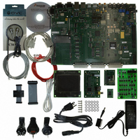
KIT APPLICATION DEV ADS I.MX27
Manufacturer
Freescale Semiconductor
Series
i.MXr
Type
Microcontrollerr
Datasheet
1.MCIMX27ADSE.pdf
(68 pages)
Specifications of MCIMX27ADSE
Contents
Main Board, LCD Panel, Keypad, NAND Flash Card, Image Sensor and TV Encoder Card
Silicon Manufacturer
Freescale
Core Architecture
ARM
Core Sub-architecture
ARM9
Silicon Core Number
I.MX2
Silicon Family Name
I.MX27
Supported Devices
I.MX27
Rohs Compliant
Yes
For Use With/related Products
i.MX27
Lead Free Status / RoHS Status
Lead free / RoHS Compliant


Chapter 2 Configuration and Operation
2.1
This section consists of configuration information, connection descriptions, and other operational
information that may be useful during the development process.
2.2
2.2.1
The four Single Pole Single Throw (SPST) slide switches of S7 control MC13783 back-up power.
Table 2-1 shows valid switch combinations (other combinations must not be used). The Super Cap backup
source is on the board. Set S7-1 and S7-3 to ON to charge the Super Cap. Variable resistor (R464) controls
peak charge and variable resistor (R463) controls charge rate. Set S7-3 to OFF when charging is complete.
Set S7-4 to ON to allow the Super Cap to discharge. The rate of discharge is controlled by R460.
Connection to an external lithium cell is optional. If a lithium cell is used, it must be connected to JP69
and S7-2 must be set to ON. Otherwise S7-2 must be OFF.
2.2.2
S18-1 to S18-4 settings determine where the processor begins program execution. Table 2-2 shows all
valid combinations of the switches. Other combinations are reserved.
Freescale Semiconductor
.
.
Introduction
Configuring Board Components
DIP Switch S7 - Li-Cell select switch
DIP Switch S18 - Boot Mode Switches
Charge Super Cap (SC1)
Hold Charge (default factory setting)
Discharge Super Cap (SC1)
External Li-Cell (JP69)
Bootstrap (USB/UART), default factory
setting
8 bit, 2K byte, NAND flash
16 bit, 2K byte, NAND flash
16 bit, 512 Byte, NAND flash
16 bit CS0 at D[15:0], NOR flash
32 bit CS0 at D[31:0], NOR flash
8 bit 512 Byte, NAND flash
Boot Mode
Function
Table 2-2. Boot Mode Switch Settings
MCIMX27ADSE User’s Manual, Rev. A
Table 2-1. Li-Cell select switch
Boot0
S18-1
S7-1
OFF
OFF
OFF
OFF
ON
ON
ON
ON
ON
ON
ON
Boot1
S18-2
S7-2
OFF
OFF
OFF
OFF
OFF
OFF
OFF
ON
ON
ON
ON
Boot2
S18-3
S7-3
OFF
OFF
OFF
OFF
OFF
OFF
OFF
ON
ON
ON
ON
Configuration and Operation
Boot3
S18-4
S7-4
OFF
OFF
OFF
ON
ON
ON
ON
ON
ON
ON
ON
2-1
Related parts for MCIMX27ADSE
Image
Part Number
Description
Manufacturer
Datasheet
Request
R

Part Number:
Description:
Multimedia Applications Processor
Manufacturer:
Freescale Semiconductor, Inc
Datasheet:
Part Number:
Description:
Manufacturer:
Freescale Semiconductor, Inc
Datasheet:
Part Number:
Description:
Manufacturer:
Freescale Semiconductor, Inc
Datasheet:
Part Number:
Description:
Manufacturer:
Freescale Semiconductor, Inc
Datasheet:
Part Number:
Description:
Manufacturer:
Freescale Semiconductor, Inc
Datasheet:
Part Number:
Description:
Manufacturer:
Freescale Semiconductor, Inc
Datasheet:
Part Number:
Description:
Manufacturer:
Freescale Semiconductor, Inc
Datasheet:
Part Number:
Description:
Manufacturer:
Freescale Semiconductor, Inc
Datasheet:
Part Number:
Description:
Manufacturer:
Freescale Semiconductor, Inc
Datasheet:
Part Number:
Description:
Manufacturer:
Freescale Semiconductor, Inc
Datasheet:
Part Number:
Description:
Manufacturer:
Freescale Semiconductor, Inc
Datasheet:
Part Number:
Description:
Manufacturer:
Freescale Semiconductor, Inc
Datasheet:
Part Number:
Description:
Manufacturer:
Freescale Semiconductor, Inc
Datasheet:
Part Number:
Description:
Manufacturer:
Freescale Semiconductor, Inc
Datasheet:
Part Number:
Description:
Manufacturer:
Freescale Semiconductor, Inc
Datasheet: