MCIMX27ADSE Freescale Semiconductor, MCIMX27ADSE Datasheet - Page 50
MCIMX27ADSE
Manufacturer Part Number
MCIMX27ADSE
Description
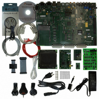
KIT APPLICATION DEV ADS I.MX27
Manufacturer
Freescale Semiconductor
Series
i.MXr
Type
Microcontrollerr
Datasheet
1.MCIMX27ADSE.pdf
(68 pages)
Specifications of MCIMX27ADSE
Contents
Main Board, LCD Panel, Keypad, NAND Flash Card, Image Sensor and TV Encoder Card
Silicon Manufacturer
Freescale
Core Architecture
ARM
Core Sub-architecture
ARM9
Silicon Core Number
I.MX2
Silicon Family Name
I.MX27
Supported Devices
I.MX27
Rohs Compliant
Yes
For Use With/related Products
i.MX27
Lead Free Status / RoHS Status
Lead free / RoHS Compliant


Support Information
3.13
P17 and P18 are the SD/MMC connectors. Figure 3-16 shows pin assignments. Table 3-16 describes P17
signals and Table 3-17 describes P18 signals.
3-16
SD/MMC Connectors
Pin(s)
10
11
12
16
The SD/MMC2 signals are multiplexed with Memory Stick signals.
Therefore, the signals from SD/MMC2 (P18) are disconnected from the
MCU by jumpers (J72-J77) in order to reduce the bus loading from Memory
Stick (J16). The jumpers need to install in J72-J77 to enable SD/MMC2.
1
2
3
4
5
6
7
8
9
CPLD_SD1_DET
CPLD_SD1_WP
Table 3-16. SD/MMC Connector P6 Signal Descriptions
PM_VMMC1
Figure 3-16. SD/MMC Connector P6 Pin Assignments
SD1_DAT3
SD1_DAT0
SD1_DAT1
SD1_DAT2
SD1_CMD
SD1_CLK
Signal
GND
GND
GND
NC
MCIMX27ADSE User’s Manual, Rev. A
12
11
10
DATA LINE 3
DATA LINE 1
DATA LINE 2
MMC Card
8
7
6
NOTE
5
WRITE PROTECT DETECT FROM CPLD
4
Card power supply from MC13783
3
CARD DETECT FROM CPLD
2
COMMAND/RESPONSE
INTERRUPT (IRQ)
READWAIT (RW)
1
NO CONNECTION
9
1-Bit Mode
CLOCK INPUT
Not Used
DATA LINE 0
Description
13
GROUND
GROUND
GROUND
16
SD Card
DATA LINE 1 or IRQ
DATA LINE 2or IRQ
DATA LINE 3
4-Bit Mode
Freescale Semiconductor
Related parts for MCIMX27ADSE
Image
Part Number
Description
Manufacturer
Datasheet
Request
R

Part Number:
Description:
Multimedia Applications Processor
Manufacturer:
Freescale Semiconductor, Inc
Datasheet:
Part Number:
Description:
Manufacturer:
Freescale Semiconductor, Inc
Datasheet:
Part Number:
Description:
Manufacturer:
Freescale Semiconductor, Inc
Datasheet:
Part Number:
Description:
Manufacturer:
Freescale Semiconductor, Inc
Datasheet:
Part Number:
Description:
Manufacturer:
Freescale Semiconductor, Inc
Datasheet:
Part Number:
Description:
Manufacturer:
Freescale Semiconductor, Inc
Datasheet:
Part Number:
Description:
Manufacturer:
Freescale Semiconductor, Inc
Datasheet:
Part Number:
Description:
Manufacturer:
Freescale Semiconductor, Inc
Datasheet:
Part Number:
Description:
Manufacturer:
Freescale Semiconductor, Inc
Datasheet:
Part Number:
Description:
Manufacturer:
Freescale Semiconductor, Inc
Datasheet:
Part Number:
Description:
Manufacturer:
Freescale Semiconductor, Inc
Datasheet:
Part Number:
Description:
Manufacturer:
Freescale Semiconductor, Inc
Datasheet:
Part Number:
Description:
Manufacturer:
Freescale Semiconductor, Inc
Datasheet:
Part Number:
Description:
Manufacturer:
Freescale Semiconductor, Inc
Datasheet:
Part Number:
Description:
Manufacturer:
Freescale Semiconductor, Inc
Datasheet: