MCIMX27ADSE Freescale Semiconductor, MCIMX27ADSE Datasheet - Page 9
MCIMX27ADSE
Manufacturer Part Number
MCIMX27ADSE
Description
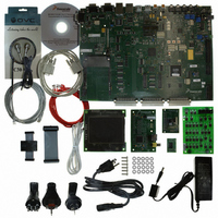
KIT APPLICATION DEV ADS I.MX27
Manufacturer
Freescale Semiconductor
Series
i.MXr
Type
Microcontrollerr
Datasheet
1.MCIMX27ADSE.pdf
(68 pages)
Specifications of MCIMX27ADSE
Contents
Main Board, LCD Panel, Keypad, NAND Flash Card, Image Sensor and TV Encoder Card
Silicon Manufacturer
Freescale
Core Architecture
ARM
Core Sub-architecture
ARM9
Silicon Core Number
I.MX2
Silicon Family Name
I.MX27
Supported Devices
I.MX27
Rohs Compliant
Yes
For Use With/related Products
i.MX27
Lead Free Status / RoHS Status
Lead free / RoHS Compliant


Chapter 1 General Information
1.1
The i.MX27 Application Development System (MCIMX27ADSE) is a development tool which is
designed to run software applications designed for i.MX27 microcontroller unit.
The MCIMX27ADSE includes a main board, an LCD display panel, a keypad, a NAND flash card, an
image sensor, a TV encoder card, etc. It supports application software, target-board debugging or optional
extra memory.
1.2
ADS features include:
Freescale Semiconductor
•
•
•
•
•
•
•
•
•
•
•
•
•
•
•
•
•
•
•
i.MX27 Multimedia Application Processor
Two clock-source crystals, 32.000 KHz and 26 MHz
Power management & Audio IC (MC13783) included battery changing, 10bit ADC, buck
switchers, boost switcher, regulators, amplifiers, CODEC, SSI audio bus, real time clock, SPI
control bus, USB OTG transceiver & touchscreen interface
Multi-ICE debug support
Two 512Mbit DDR-SDRAM devices, configured as one 128MB, 32-bit device
One 256Mbit Burst Flash with 128Mbit Pseudo Static RAM (PSRAM) memory device, configured
as one 16MB flash with 8MB PSRAM, 16-bit device
An single board system with connections for LCD display panel, Keypad and Image sensor.
Complex Programmable Logic Device (CPLD) for reducing the glue logics
Software readable board revisions
Configuration and user definable DIP switches
Two SD/MMC, MS memory card connectors
PCMCIA & ATA Hard Disk Drive (HDD)
Two RS-232 transceivers and DB9 connectors (one configured for DCE and one for DTE
operation) supporting on-chip UART ports
External UART with RS-232 transceiver and DB9 connector
Infrared transceiver that conforms to Specification 1.4 of the Infrared Data Association
USB Host (HS & FS), USB OTG (HS & HS) interface
Separate LCD panel assembly that connects to the main board
Separate keypad unit with 36 push button keys
Separate CMOS Image Sensor Card
Description
MCIMX27ADSE Features
MCIMX27ADSE User’s Manual, Rev. A
1-1
Related parts for MCIMX27ADSE
Image
Part Number
Description
Manufacturer
Datasheet
Request
R

Part Number:
Description:
Multimedia Applications Processor
Manufacturer:
Freescale Semiconductor, Inc
Datasheet:
Part Number:
Description:
Manufacturer:
Freescale Semiconductor, Inc
Datasheet:
Part Number:
Description:
Manufacturer:
Freescale Semiconductor, Inc
Datasheet:
Part Number:
Description:
Manufacturer:
Freescale Semiconductor, Inc
Datasheet:
Part Number:
Description:
Manufacturer:
Freescale Semiconductor, Inc
Datasheet:
Part Number:
Description:
Manufacturer:
Freescale Semiconductor, Inc
Datasheet:
Part Number:
Description:
Manufacturer:
Freescale Semiconductor, Inc
Datasheet:
Part Number:
Description:
Manufacturer:
Freescale Semiconductor, Inc
Datasheet:
Part Number:
Description:
Manufacturer:
Freescale Semiconductor, Inc
Datasheet:
Part Number:
Description:
Manufacturer:
Freescale Semiconductor, Inc
Datasheet:
Part Number:
Description:
Manufacturer:
Freescale Semiconductor, Inc
Datasheet:
Part Number:
Description:
Manufacturer:
Freescale Semiconductor, Inc
Datasheet:
Part Number:
Description:
Manufacturer:
Freescale Semiconductor, Inc
Datasheet:
Part Number:
Description:
Manufacturer:
Freescale Semiconductor, Inc
Datasheet:
Part Number:
Description:
Manufacturer:
Freescale Semiconductor, Inc
Datasheet: