MCIMX27ADSE Freescale Semiconductor, MCIMX27ADSE Datasheet - Page 45
MCIMX27ADSE
Manufacturer Part Number
MCIMX27ADSE
Description
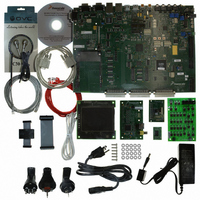
KIT APPLICATION DEV ADS I.MX27
Manufacturer
Freescale Semiconductor
Series
i.MXr
Type
Microcontrollerr
Datasheet
1.MCIMX27ADSE.pdf
(68 pages)
Specifications of MCIMX27ADSE
Contents
Main Board, LCD Panel, Keypad, NAND Flash Card, Image Sensor and TV Encoder Card
Silicon Manufacturer
Freescale
Core Architecture
ARM
Core Sub-architecture
ARM9
Silicon Core Number
I.MX2
Silicon Family Name
I.MX27
Supported Devices
I.MX27
Rohs Compliant
Yes
For Use With/related Products
i.MX27
Lead Free Status / RoHS Status
Lead free / RoHS Compliant


3.9
PM1 and PM2 on the CPU board allow the ADS to interface with a NAND Flash module. Figure 3-11 and
Figure 3-12 show pin assignments for PM1 and PM2 respectively. Table 3-11 and Table 3-12 provide
signal descriptions for the PM1 and PM2 connector respectively.
Freescale Semiconductor
NAND Flash Connectors
2, 11, 13, 15
17, 18, 19,
Figure 3-11. NAND Flash Connector PM1 (on the CPU Board) Pin Assignments
Pin(s)
10
12
14
16
20
1
3
4
5
6
7
8
9
Table 3-11. NAND Flash Connector PM1 Signal Descriptions
CVDD_2.775V
DVDD_1.8V
BNFWE_B
BNFWP_B
BNFRE_B
BNFCE_B
BNFCLE
BNFALE
BNFRB
Signal
TP98
TP77
3V15
GND
NC
CVDD_2.775V
DVDD_1.8V
NF_DET_B
MCIMX27ADSE User’s Manual, Rev. A
TP98
TP77
3V15
GND
NC
NC
NC
+1.8 VDC power
Not Connect
Test point
BUFFERED NAND FLASH READY/BUSY
+ 2.775 VDC power
NAND FLASH READ ENABLE
Test point
BUFFERED NAND FLASH CHIP ENABLE
+3.15 VDC power
BUFFERED NAND FLASH COMMAND LATCH ENABLE
BUFFERED NAND FLASH ADDRESS LATCH ENABLE
BUFFERED NAND FLASH WRITE ENABLE
BUFFERED NAND FLASH WRITE PROTECT
GROUND
11
13
15
17
19
1
3
5
7
9
PM1
• •
• •
• •
• •
• •
• •
• •
• •
• •
• •
10
12
14
16
18
20
2
4
6
8
NC
BNFRB
BNFRE_B
BNFCE_B
BNFCLE
BNFALE
BNFWE_B
BNFWP_B
GND
GND
Description
Support Information
3-11
Related parts for MCIMX27ADSE
Image
Part Number
Description
Manufacturer
Datasheet
Request
R

Part Number:
Description:
Multimedia Applications Processor
Manufacturer:
Freescale Semiconductor, Inc
Datasheet:
Part Number:
Description:
Manufacturer:
Freescale Semiconductor, Inc
Datasheet:
Part Number:
Description:
Manufacturer:
Freescale Semiconductor, Inc
Datasheet:
Part Number:
Description:
Manufacturer:
Freescale Semiconductor, Inc
Datasheet:
Part Number:
Description:
Manufacturer:
Freescale Semiconductor, Inc
Datasheet:
Part Number:
Description:
Manufacturer:
Freescale Semiconductor, Inc
Datasheet:
Part Number:
Description:
Manufacturer:
Freescale Semiconductor, Inc
Datasheet:
Part Number:
Description:
Manufacturer:
Freescale Semiconductor, Inc
Datasheet:
Part Number:
Description:
Manufacturer:
Freescale Semiconductor, Inc
Datasheet:
Part Number:
Description:
Manufacturer:
Freescale Semiconductor, Inc
Datasheet:
Part Number:
Description:
Manufacturer:
Freescale Semiconductor, Inc
Datasheet:
Part Number:
Description:
Manufacturer:
Freescale Semiconductor, Inc
Datasheet:
Part Number:
Description:
Manufacturer:
Freescale Semiconductor, Inc
Datasheet:
Part Number:
Description:
Manufacturer:
Freescale Semiconductor, Inc
Datasheet:
Part Number:
Description:
Manufacturer:
Freescale Semiconductor, Inc
Datasheet: