MCIMX27ADSE Freescale Semiconductor, MCIMX27ADSE Datasheet - Page 16
MCIMX27ADSE
Manufacturer Part Number
MCIMX27ADSE
Description
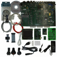
KIT APPLICATION DEV ADS I.MX27
Manufacturer
Freescale Semiconductor
Series
i.MXr
Type
Microcontrollerr
Datasheet
1.MCIMX27ADSE.pdf
(68 pages)
Specifications of MCIMX27ADSE
Contents
Main Board, LCD Panel, Keypad, NAND Flash Card, Image Sensor and TV Encoder Card
Silicon Manufacturer
Freescale
Core Architecture
ARM
Core Sub-architecture
ARM9
Silicon Core Number
I.MX2
Silicon Family Name
I.MX27
Supported Devices
I.MX27
Rohs Compliant
Yes
For Use With/related Products
i.MX27
Lead Free Status / RoHS Status
Lead free / RoHS Compliant


Configuration and Operation
S18-5 selects the JTAG operation mode and S18-6 is reserved. Table 2-3 shows the functionality.
2.2.3
S9-1 to S9-4 control USB port functions. Table 2-4 shows the valid switch combinations.
S9-5 ON disables the MC13783’s USB OTG transceiver, OFF enables it. This device is disabled in the
default factory setting. S9-6 is not used in the ADS.
2.2.4
The six SPST slide switches in S3 control the source of the CLIA and CLIB audio bus clock inputs of the
MC13783. Table 2-5 and Table 2-6 show the valid switch functions.
2-2
.
DIP Switch S9 - MC13783 USB Mode Switches
DIP Switch S3 - MC13783 Audio Clock Source Select
S18-5, JTAG _CTRL
S18-6, NC
Differential, Unidirectional (6 wire)
Differential, Bidirectional (4 wire)
Single Ended, Unidirectional (6 wire)
Single Ended, Bidirectional (4 wire)
The MC13783 OTG transceiver disconnects from i.MX27 CPU by RP24
and RP25. Because Philips ISP1301 (U37) is the default OTG transceiver in
the ADS. If the user needs to use the USBOTG connector (J92), RP24 and
RP25 needs to be installed and RP3-5 and RP11-12 removed
Switch Name
CLKO (Pin AD17 of MX27, U1); default
factory setting.
On-board 26MHz oscillator (Y9)
External clock input from JP70
CLKO (Pin AD17 of MX27, U1); default
factory setting.
On-board 26MHz oscillator (Y9)
External clock input from JP70
USB Mode Select
CLIA clock source
CLIB clock source
Table 2-3. S18-5 and S18-6 Switch Settings
Table 2-4. MC13783 USB Mode Switches
Table 2-5. MC13783 CLIA Source Select
Table 2-6. MC13783 CLIB Source Select
ON
OFF
-
MCIMX27ADSE User’s Manual, Rev. A
Setting
Internal test only.
ARM Multi-ICE mode selected after TRST; default
factory setting.
No Connection
NOTE
S9-1
OFF
OFF
OFF
ON
S3-1
OFF
S3-2
OFF
OFF
OFF
ON
ON
S9-2
OFF
OFF
OFF
ON
Effect
S3-3
S3-4
OFF
OFF
OFF
OFF
ON
ON
S9-3
OFF
OFF
OFF
ON
S3-5
OFF
S3-6
OFF
OFF
OFF
ON
ON
Freescale Semiconductor
S9-4
OFF
ON
ON
ON
Related parts for MCIMX27ADSE
Image
Part Number
Description
Manufacturer
Datasheet
Request
R

Part Number:
Description:
Multimedia Applications Processor
Manufacturer:
Freescale Semiconductor, Inc
Datasheet:
Part Number:
Description:
Manufacturer:
Freescale Semiconductor, Inc
Datasheet:
Part Number:
Description:
Manufacturer:
Freescale Semiconductor, Inc
Datasheet:
Part Number:
Description:
Manufacturer:
Freescale Semiconductor, Inc
Datasheet:
Part Number:
Description:
Manufacturer:
Freescale Semiconductor, Inc
Datasheet:
Part Number:
Description:
Manufacturer:
Freescale Semiconductor, Inc
Datasheet:
Part Number:
Description:
Manufacturer:
Freescale Semiconductor, Inc
Datasheet:
Part Number:
Description:
Manufacturer:
Freescale Semiconductor, Inc
Datasheet:
Part Number:
Description:
Manufacturer:
Freescale Semiconductor, Inc
Datasheet:
Part Number:
Description:
Manufacturer:
Freescale Semiconductor, Inc
Datasheet:
Part Number:
Description:
Manufacturer:
Freescale Semiconductor, Inc
Datasheet:
Part Number:
Description:
Manufacturer:
Freescale Semiconductor, Inc
Datasheet:
Part Number:
Description:
Manufacturer:
Freescale Semiconductor, Inc
Datasheet:
Part Number:
Description:
Manufacturer:
Freescale Semiconductor, Inc
Datasheet:
Part Number:
Description:
Manufacturer:
Freescale Semiconductor, Inc
Datasheet: