MCIMX27ADSE Freescale Semiconductor, MCIMX27ADSE Datasheet - Page 31
MCIMX27ADSE
Manufacturer Part Number
MCIMX27ADSE
Description
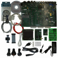
KIT APPLICATION DEV ADS I.MX27
Manufacturer
Freescale Semiconductor
Series
i.MXr
Type
Microcontrollerr
Datasheet
1.MCIMX27ADSE.pdf
(68 pages)
Specifications of MCIMX27ADSE
Contents
Main Board, LCD Panel, Keypad, NAND Flash Card, Image Sensor and TV Encoder Card
Silicon Manufacturer
Freescale
Core Architecture
ARM
Core Sub-architecture
ARM9
Silicon Core Number
I.MX2
Silicon Family Name
I.MX27
Supported Devices
I.MX27
Rohs Compliant
Yes
For Use With/related Products
i.MX27
Lead Free Status / RoHS Status
Lead free / RoHS Compliant


2.4.4
Connector J12 is pre-configured to operate directly with the IM8012 image sensor module supplied with
the ADS. Communication with this card takes place through the I
operation, refer to the data sheet on the documentation CD.
To install the image sensor card, plug its 48 position DIN connector into J12 of the ADS board. When the
image sensor card is installed, the two boards are at a right angle to each other, with the image sensor facing
away from the ADS as shown in Figure 2-15.
2.4.5
A TV encoder card comes with the ADS. The main component is a FS453LF (PC to TV Video Scan
converter) from FOCUS Enhancements Semiconductor. For details on TV encoder operation, refer to its
data sheet, available at http://www.focusinfo.com/
Freescale Semiconductor
Using an Image Sensor Module
Using a TV Encoder Card
To avoid circuit damage, do not plug-in the image sensor card with power
applied to the board.
Make sure that input power is disconnected or switched off before the TV
encoder card is installed. Connecting the card with power applied can
damage the TV encoder card and the ADS board.
IMAGE SENSOR
J12
Figure 2-15. Installing the image sensor module
MCIMX27ADSE User’s Manual, Rev. A
P8
CAUTION
CAUTION
i.MX27ADS
J13
P9
2
PM2
C interface. For details on image sensor
J14
PM1
Configuration and Operation
S15
2-17
Related parts for MCIMX27ADSE
Image
Part Number
Description
Manufacturer
Datasheet
Request
R

Part Number:
Description:
Multimedia Applications Processor
Manufacturer:
Freescale Semiconductor, Inc
Datasheet:
Part Number:
Description:
Manufacturer:
Freescale Semiconductor, Inc
Datasheet:
Part Number:
Description:
Manufacturer:
Freescale Semiconductor, Inc
Datasheet:
Part Number:
Description:
Manufacturer:
Freescale Semiconductor, Inc
Datasheet:
Part Number:
Description:
Manufacturer:
Freescale Semiconductor, Inc
Datasheet:
Part Number:
Description:
Manufacturer:
Freescale Semiconductor, Inc
Datasheet:
Part Number:
Description:
Manufacturer:
Freescale Semiconductor, Inc
Datasheet:
Part Number:
Description:
Manufacturer:
Freescale Semiconductor, Inc
Datasheet:
Part Number:
Description:
Manufacturer:
Freescale Semiconductor, Inc
Datasheet:
Part Number:
Description:
Manufacturer:
Freescale Semiconductor, Inc
Datasheet:
Part Number:
Description:
Manufacturer:
Freescale Semiconductor, Inc
Datasheet:
Part Number:
Description:
Manufacturer:
Freescale Semiconductor, Inc
Datasheet:
Part Number:
Description:
Manufacturer:
Freescale Semiconductor, Inc
Datasheet:
Part Number:
Description:
Manufacturer:
Freescale Semiconductor, Inc
Datasheet:
Part Number:
Description:
Manufacturer:
Freescale Semiconductor, Inc
Datasheet: