MCIMX27ADSE Freescale Semiconductor, MCIMX27ADSE Datasheet - Page 32
MCIMX27ADSE
Manufacturer Part Number
MCIMX27ADSE
Description
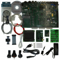
KIT APPLICATION DEV ADS I.MX27
Manufacturer
Freescale Semiconductor
Series
i.MXr
Type
Microcontrollerr
Datasheet
1.MCIMX27ADSE.pdf
(68 pages)
Specifications of MCIMX27ADSE
Contents
Main Board, LCD Panel, Keypad, NAND Flash Card, Image Sensor and TV Encoder Card
Silicon Manufacturer
Freescale
Core Architecture
ARM
Core Sub-architecture
ARM9
Silicon Core Number
I.MX2
Silicon Family Name
I.MX27
Supported Devices
I.MX27
Rohs Compliant
Yes
For Use With/related Products
i.MX27
Lead Free Status / RoHS Status
Lead free / RoHS Compliant


Configuration and Operation
This TV encoder cannot be used at the same time as the LCD display because they share connector P14
on the ADS board. To use the TV encoder module, you must disconnect the LCD board from P14 on the
ADS board and install the TV encoder module in P14 and P15 of the ADS board as shown in Figure 2-16.
2.4.6
Three plug-in memory cards support by the ADS: a memory stick and two SD/MMC cards. The
corresponding card holders, connectors J16, P17, and P18, are on the bottom of the board. The same
i.MX27 signals control the memory stick connector J16 and SD/MMC2 connector P18. In order to reduce
the bus loading, the signals from SD/MMC2 connector disconnected by the headers J72-J77. To direct
these signals to P18 (that is, to use SD/MMC2 cards), insert jumpers into these connectors
Interface signals are provided by the i.MX27 but write protect but the card detect inputs are read through
the CPLD.
2-18
Using Plug-in Memory Cards
Since the signals of the memory stick and SD/MMC2 are multiplexed in
i.MX27, it cannot use both memory cards at the same time.
Figure 2-16. Installing the TV Encoder Card
MCIMX27ADSE User’s Manual, Rev. A
J14
R425
JP65
P14
P15
P22
NOTE
J91
CN5
P1
P2
J2
J3
J1
Freescale Semiconductor
Related parts for MCIMX27ADSE
Image
Part Number
Description
Manufacturer
Datasheet
Request
R

Part Number:
Description:
Multimedia Applications Processor
Manufacturer:
Freescale Semiconductor, Inc
Datasheet:
Part Number:
Description:
Manufacturer:
Freescale Semiconductor, Inc
Datasheet:
Part Number:
Description:
Manufacturer:
Freescale Semiconductor, Inc
Datasheet:
Part Number:
Description:
Manufacturer:
Freescale Semiconductor, Inc
Datasheet:
Part Number:
Description:
Manufacturer:
Freescale Semiconductor, Inc
Datasheet:
Part Number:
Description:
Manufacturer:
Freescale Semiconductor, Inc
Datasheet:
Part Number:
Description:
Manufacturer:
Freescale Semiconductor, Inc
Datasheet:
Part Number:
Description:
Manufacturer:
Freescale Semiconductor, Inc
Datasheet:
Part Number:
Description:
Manufacturer:
Freescale Semiconductor, Inc
Datasheet:
Part Number:
Description:
Manufacturer:
Freescale Semiconductor, Inc
Datasheet:
Part Number:
Description:
Manufacturer:
Freescale Semiconductor, Inc
Datasheet:
Part Number:
Description:
Manufacturer:
Freescale Semiconductor, Inc
Datasheet:
Part Number:
Description:
Manufacturer:
Freescale Semiconductor, Inc
Datasheet:
Part Number:
Description:
Manufacturer:
Freescale Semiconductor, Inc
Datasheet:
Part Number:
Description:
Manufacturer:
Freescale Semiconductor, Inc
Datasheet: