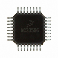
MC33596FJE Freescale Semiconductor, MC33596FJE Datasheet - Page 16

MC33596FJE
Manufacturer Part Number
MC33596FJE
Description
IC RECEIVER UHF PLL TUNED 32LQFP
Manufacturer
Freescale Semiconductor
Type
Receiverr
Datasheet
1.MC33596FCAE.pdf
(70 pages)
Specifications of MC33596FJE
Frequency
304, 315, 426, 434, 868 & 915MHz
Sensitivity
-104dBm
Data Rate - Maximum
22.4 kBaud
Modulation Or Protocol
FSK, OOK
Applications
General Data Transfer
Current - Receiving
10.3mA
Data Interface
PCB, Surface Mount
Antenna Connector
PCB, Surface Mount
Voltage - Supply
2.7 V ~ 3.6 V, 4.5 V ~ 5.5 V
Operating Temperature
-40°C ~ 85°C
Package / Case
32-LQFP
Operating Frequency
915 MHz
Operating Supply Voltage
3.3 V or 5 V
Maximum Operating Temperature
+ 85 C
Minimum Operating Temperature
- 40 C
Mounting Style
SMD/SMT
Operating Temperature (min)
-40C
Operating Temperature (max)
85C
Operating Temperature Classification
Industrial
Modulation Type
FSK/OOK
Package Type
LQFP
Operating Supply Voltage (min)
2.7V
Lead Free Status / RoHS Status
Lead free / RoHS Compliant
Features
-
Memory Size
-
Lead Free Status / Rohs Status
Lead free / RoHS Compliant
Available stocks
Company
Part Number
Manufacturer
Quantity
Price
Part Number:
MC33596FJE
Manufacturer:
FREESCALE
Quantity:
20 000
Part Number:
MC33596FJER2
Manufacturer:
FREESCALE
Quantity:
20 000
Receive Mode
11.2.3.2 ID
When clock recovery is done, the data manager verifies if an ID is received. The ID is used to identify a
useful frame to receive. It is also necessary, when the receiver is strobed, to detect an ID in order to stay
in run mode and not miss the frame.
The ID allows selection of the correct device in an RF transmission, as the content has been loaded
previously in the ID register. Its length is variable, defined by the IDL[1:0] bits. The complement of the
ID is also recognized as the identifier.
It is possible to build a tone to form the detection sequence by programming the ID register with a full
sequence of ones or zeroes.
Once the ID is detected, a HEADER will be searched to detect the beginning of the useful data to send on
the SPI port.
See
detected when SOE=1 or SOE=0.
16
Section 11.2.4, “State Machine in Receive Mode When
NOTES:
1. The AGC settling time pulse can be split over different pulses as long as the overall duration is at least 200 μs.
2.
3. The Manchester 0 symbol can be replaced by a 1.
OOK MODULATION (DSREF = 0)
OOK MODULATION (DSREF = 0)
OOK MODULATION (DSREF = 1)
OOK MODULATION (DSREF = 1)
FSK MODULATION (DSREF = 1)
FSK MODULATION (DSREF = 1)
The 200 μs pulse may be replaced by : (1 bit @ 2400 bps or 2 bits @ 4800 bps or 4 bits @ 9600 bps or 8 bits @ 19200 bps).
Table 13
frequencies.
Data Slicer Reference Settling Time
Data Slicer Reference Settling Time
1 NRZ >
1 NRZ >
1 NRZ >
1 NRZ >
defines the minimum number of Manchester symbols required for the data slicer operation versus the data and average filter cut-off
AGC Settling Time
AGC Settling Time
AGC Settling Time
AGC Settling Time
At Least 3 Manchester
At Least 3 Manchester
at Data Rate (2 and 3)
at Data Rate (2 and 3)
200
200
200
200
0 Symbols
0 Symbols
μs (1)
μs (1)
μs (1)
μs (1)
Clock Recovery
Clock Recovery
1 Manchester
1 Manchester
at Data Rate
at Data Rate
‘0’ Symbol
‘0’ Symbol
Data Slicer Reference Settling Time
Data Slicer Reference Settling Time
Figure 9. Preamble Definition
MC33596 Data Sheet, Rev. 4
Clock Recovery
Clock Recovery
at Data Rate (3)
at Data Rate (3)
At Least 3 Manchester
At Least 3 Manchester
at Data Rate (2 and 3)
at Data Rate (2 and 3)
1 Manchester
1 Manchester
0 Symbol
0 Symbol
0 Symbols
0 Symbols
ID
ID
DME=1” for more details when ID is not
ID
ID
Clock Recovery
Clock Recovery
at Data Rate (3)
at Data Rate (3)
1 Manchester
1 Manchester
0 Symbol
0 Symbol
Freescale Semiconductor
ID
ID


