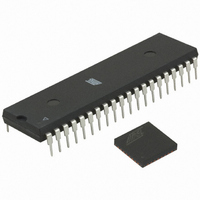
ATMEGA64RZAV-10PU Atmel, ATMEGA64RZAV-10PU Datasheet - Page 21

ATMEGA64RZAV-10PU
Manufacturer Part Number
ATMEGA64RZAV-10PU
Description
MCU ATMEGA644/AT86RF230 40-DIP
Manufacturer
Atmel
Series
ATMEGAr
Datasheets
1.ATMEGA644-20MU.pdf
(23 pages)
2.ATMEGA644-20MU.pdf
(376 pages)
3.AT86RF230-ZU.pdf
(98 pages)
Specifications of ATMEGA64RZAV-10PU
Frequency
2.4GHz
Modulation Or Protocol
802.15.4 Zigbee
Power - Output
3dBm
Sensitivity
-101dBm
Voltage - Supply
1.8 V ~ 3.6 V
Data Interface
PCB, Surface Mount
Memory Size
64kB Flash, 2kB EEPROM, 4kB RAM
Antenna Connector
PCB, Surface Mount
Package / Case
40-DIP (0.600", 15.24mm)
Wireless Frequency
2.4 GHz
Interface Type
JTAG, SPI
Output Power
3 dBm
For Use With
ATSTK600-TQFP32 - STK600 SOCKET/ADAPTER 32-TQFPATAVRISP2 - PROGRAMMER AVR IN SYSTEMATSTK500 - PROGRAMMER AVR STARTER KIT
Lead Free Status / RoHS Status
Lead free / RoHS Compliant
Operating Temperature
-
Applications
-
Data Rate - Maximum
-
Current - Transmitting
-
Current - Receiving
-
Lead Free Status / Rohs Status
Lead free / RoHS Compliant
For Use With/related Products
ATmega64
7 Operating Modes
7.1 Basic Operating Mode
Figure 7-1. Basic Operating Mode State Diagram (for State Transition Timing Data Refer to Table 7-1)
7.1.1 State Control
5131E-MCU Wireless-02/09
This section summarizes all states to provide the basic functionality of the AT86RF230,
such as receiving and transmitting frames, and powering up and down. The Basic
Operating Mode is designed for IEEE 802.15.4 applications; the corresponding radio
transceiver states are shown in Figure 7-1.
The radio transceiver state is controlled by two signal pins (SLP_TR, RST ) and the
register 0x02 (TRX_STATE). A successful state change shall be confirmed by reading
the radio transceiver status from register 0x01 (TRX_STATUS).
If TRX_STATUS = 0x1F (STATE_TRANSITION_IN_PROGRESS) the AT86RF230 is
on a state transition. Do not try to initiate a further state change while the radio
transceiver is in STATE_TRANSITION_IN_PROGRESS.
AT86RF230
21


