ATMEGA64RZAV-10PU Atmel, ATMEGA64RZAV-10PU Datasheet - Page 26
ATMEGA64RZAV-10PU
Manufacturer Part Number
ATMEGA64RZAV-10PU
Description
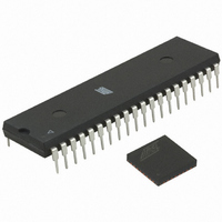
MCU ATMEGA644/AT86RF230 40-DIP
Manufacturer
Atmel
Series
ATMEGAr
Datasheets
1.ATMEGA644-20MU.pdf
(23 pages)
2.ATMEGA644-20MU.pdf
(376 pages)
3.AT86RF230-ZU.pdf
(98 pages)
Specifications of ATMEGA64RZAV-10PU
Frequency
2.4GHz
Modulation Or Protocol
802.15.4 Zigbee
Power - Output
3dBm
Sensitivity
-101dBm
Voltage - Supply
1.8 V ~ 3.6 V
Data Interface
PCB, Surface Mount
Memory Size
64kB Flash, 2kB EEPROM, 4kB RAM
Antenna Connector
PCB, Surface Mount
Package / Case
40-DIP (0.600", 15.24mm)
Wireless Frequency
2.4 GHz
Interface Type
JTAG, SPI
Output Power
3 dBm
For Use With
ATSTK600-TQFP32 - STK600 SOCKET/ADAPTER 32-TQFPATAVRISP2 - PROGRAMMER AVR IN SYSTEMATSTK500 - PROGRAMMER AVR STARTER KIT
Lead Free Status / RoHS Status
Lead free / RoHS Compliant
Operating Temperature
-
Applications
-
Data Rate - Maximum
-
Current - Transmitting
-
Current - Receiving
-
Lead Free Status / Rohs Status
Lead free / RoHS Compliant
For Use With/related Products
ATmega64


7.1.4.2 Reset Procedure
7.1.4.3 State Transition Timing
Table 7-1. State Transition Timing
26
No
1
2
3
4
Symbol
t
t
t
t
TR1
TR2
TR3
TR4
AT86RF230
Transition
P_ON
SLEEP
TRX_OFF →
TRX_OFF →
→
→
In TRX_OFF state, entering the commands PLL_ON or RX_ON initiates a ramp-up
sequence of the analog voltage regulator. RX_ON state can be entered any time during
PLL_ON state regardless whether the PLL has already locked.
When the wake-up sequence is started from P_ON state (V
transceiver) the state machine stops after the 128 µs timer expires to wait for a valid
TRX_OFF command from the microcontroller. The default CLKM frequency in P_ON
state is 1 MHz.
bits CLKM_CTRL of register 0x03 (TRX_CTRL_0) are shadowed at reset. For details
refer to section 9.6.4.
After releasing the reset pin ( RST = H) a calibration cycle of the FTN is started and the
digital voltage regulator is turned on. The state TRX_OFF is entered and the status of
the main state machine changes from STATE_TRANSITION_IN_PROGRESS to
TRX_OFF.
This sequence is identical for all radio transceiver states except in state P_ON. The
state machine does not leave the state P_ON after a reset in this state. Instead, the
procedure described in section 7.1.2.1 must be followed to enter the TRX_OFF state for
the very first time. Figure 7-4 describes the reset procedure once the P_ON state was
left.
Note that the access to the device should not occur earlier than 625 ns after releasing
the reset pin. During the reset procedure the SPI interface shall be inactive ( SEL = H;
SCLK = L).
Figure 7-4. Reset Procedure
The transition numbers (first column) in Table 7-1 correspond to Figure 7-1 and do not
include SPI access time if not otherwise stated. See measurement setup in Figure 5-1.
Signals/Events
State
RST = L sets all registers to their default values (see Table 12-2). Exception, register
Active Blocks
Command
Pin
TRX_OFF
TRX_OFF
SLEEP
PLL_ON
0 20
RESET
RST=0
XOSC
Time [µs]
(tppical)
880
880
180
35
x
FTN BG
RST=1
Comments
Depends on external bypass capacitor at DVDD (1 µF nom)
and crystal oscillator setup (CL = 10 pF)
Depends on external bypass capacitor at DVDD (1 µF nom)
and crystal oscillator setup (CL = 10 pF)
f
Depends on external bypass capacitor at AVDD (1 µF nom).
CLKM
DVREG
x+100
= 1 MHz
TRX_OFF
Time [μs]
Time [μs]
DD
first applied to the radio
Typical block settling time, stays on
Block active
waiting for SPI commands
5131E-MCU Wireless-02/09
Related parts for ATMEGA64RZAV-10PU
Image
Part Number
Description
Manufacturer
Datasheet
Request
R

Part Number:
Description:
DEV KIT FOR AVR/AVR32
Manufacturer:
Atmel
Datasheet:

Part Number:
Description:
INTERVAL AND WIPE/WASH WIPER CONTROL IC WITH DELAY
Manufacturer:
ATMEL Corporation
Datasheet:
Part Number:
Description:
Low-Voltage Voice-Switched IC for Hands-Free Operation
Manufacturer:
ATMEL Corporation
Datasheet:
Part Number:
Description:
MONOLITHIC INTEGRATED FEATUREPHONE CIRCUIT
Manufacturer:
ATMEL Corporation
Datasheet:
Part Number:
Description:
AM-FM Receiver IC U4255BM-M
Manufacturer:
ATMEL Corporation
Datasheet:
Part Number:
Description:
Monolithic Integrated Feature Phone Circuit
Manufacturer:
ATMEL Corporation
Datasheet:
Part Number:
Description:
Multistandard Video-IF and Quasi Parallel Sound Processing
Manufacturer:
ATMEL Corporation
Datasheet:
Part Number:
Description:
High-performance EE PLD
Manufacturer:
ATMEL Corporation
Datasheet:
Part Number:
Description:
8-bit Flash Microcontroller
Manufacturer:
ATMEL Corporation
Datasheet:
Part Number:
Description:
2-Wire Serial EEPROM
Manufacturer:
ATMEL Corporation
Datasheet: