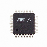
AT86RF211SAH-R Atmel, AT86RF211SAH-R Datasheet - Page 15

AT86RF211SAH-R
Manufacturer Part Number
AT86RF211SAH-R
Description
IC RF TXRX FSK 400-950MHZ 48TQFP
Manufacturer
Atmel
Datasheet
1.AT86RF211SDK.pdf
(66 pages)
Specifications of AT86RF211SAH-R
Frequency
400MHz ~ 950MHz
Data Rate - Maximum
100kbps
Modulation Or Protocol
FSK
Applications
ISM
Power - Output
7dBm ~ 12dBm
Sensitivity
-107dBm
Voltage - Supply
2.4 V ~ 3.6 V
Data Interface
PCB, Surface Mount
Antenna Connector
PCB, Surface Mount
Operating Temperature
-40°C ~ 85°C
Package / Case
48-TQFP Exposed Pad, 48-eTQFP, 48-HTQFP, 48-VQFP
Lead Free Status / RoHS Status
Contains lead / RoHS non-compliant
Memory Size
-
Current - Transmitting
-
Current - Receiving
-
2.2.3
Figure 2-6.
2.2.4
5348B–WIRE–03/06
Image Rejection and RF Filter
First LNA/Mixer
Typical 50Ω SAW Filter Implementation in the 868 MHz Bandwidth
SWOUT (pin 48)
SPST Switch
The immunity of the AT86RF211S can be improved with an external band-pass filter.
For example, when using a SAW filter, it must be matched with the LNA input and the
output of the switch. The following diagram gives the typical implementation for an
868 MHz application with a 50Ω/50Ω SAW filter.
See Table 2-2 on page 15 for precise matching information and the Application Note
“AT86RF211S FSK Transceiver for ISM Radio Applications - RF BOM vs. Application
Requirements” reference 5305, for suggested matching filters.
The LNA mixer exhibits a gain of approximately 17 dB (13 dB if the reduced gain is
selected) over a 1.2 GHz bandwidth. Its noise figure is typically 9 dB at 900 MHz (10 dB
with a minimum gain) when optimum matching is realized on pin 45:
Table 2-2.
Notes:
The gain is programmable through the CTRL1[25] register (6 dB attenuation when the
minimum gain is selected). The matching choice of the switch and LNA depends mainly
on the choice of SAW filter. Usually the in/out impedance of the SAW filter is 50Ω, but
other SAW filters can be implemented and the matching network recalculated by using
the impedance information in Table 2-2.
The LNA is directly coupled to the first mixer. The inputs and outputs of the LNA and
mixer respectively must be connected through a capacitive link because of their internal
DC coupling. A SAW or ceramic filter provides such a link.
2.2 nH
Frequency Band
1. RXIN: impedance to be seen by LNA input for NF optimization purposes
2. SWOUT: output impedance of the RF switch
433 MHz
868 MHz
915 MHz
Matching Information
These inductors can be printed
SAW
50 Ω
35 + j 170Ω
37 + j 85 Ω
30 + j 85 Ω
RXIN
12 nH
(1)
(pin 45)
RXIN
AT86RF211S
24 - j 43 Ω
50 - j 42 Ω
50 - j 42 Ω
SWOUT
(2)
15


