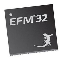
EFM32TG210F32 Energy Micro, EFM32TG210F32 Datasheet - Page 257

EFM32TG210F32
Manufacturer Part Number
EFM32TG210F32
Description
MCU 32BIT 32KB FLASH 32-QFN
Manufacturer
Energy Micro
Series
Tiny Geckor
Specifications of EFM32TG210F32
Core Processor
ARM® Cortex-M3™
Core Size
32-Bit
Speed
32MHz
Connectivity
EBI/EMI, I²C, IrDA, SmartCard, SPI, UART/USART
Peripherals
Brown-out Detect/Reset, DMA, POR, PWM, WDT
Number Of I /o
24
Program Memory Size
32KB (32K x 8)
Program Memory Type
FLASH
Ram Size
4K x 8
Voltage - Supply (vcc/vdd)
1.8 V ~ 3.8 V
Data Converters
A/D 4x12b, D/A 1x12b
Oscillator Type
External
Operating Temperature
-40°C ~ 85°C
Package / Case
32-VQFN Exposed Pad
Processor Series
EFM32
Core
ARM Cortex-M3
Data Bus Width
32 bit
Data Ram Size
32 KB
Interface Type
UART, I2C, SPI
Maximum Clock Frequency
32 MHz
Number Of Programmable I/os
17
Number Of Timers
1
Operating Supply Voltage
1.8 V to 3.8 V
Maximum Operating Temperature
+ 85 C
Mounting Style
SMD/SMT
Processor To Be Evaluated
EFM32TG210
Lead Free Status / RoHS Status
Lead free / RoHS Compliant
Eeprom Size
-
Lead Free Status / Rohs Status
Details
- Current page: 257 of 522
- Download datasheet (9Mb)
17.3.3 Debug Mode
17.3.4 Interrupts, DMA and PRS Output
17.3.5 GPIO Input/Output
2010-12-21 - d0034_Rev0.90
TIMER 2x Mode PWM Frequency Equation( Up/Down-count)
The high duty cycle is given by Equation 17.14 (p. 257)
TIMER 2x Mode Duty Cycle Equation
When the CPU is halted in debug mode, the Timer can be configured to either continue to run or to be
frozen. This is configured in DBGHALT in TIMERn_CTRL.
The Timer has 5 output events:
• Counter Underflow
• Counter Overflow
• Compare match or input capture (one per Compare/Capture channel)
Each of the events has its own interrupt flag. Also, there is one interrupt flag for each Compare/Capture
channel which is set on buffer overflow in capture mode. Buffer overflow happens when a new capture
pushes an old unread capture out of the TIMERn_CCx_CCV/TIMERn_CCx_CCVB register pair.
If the interrupt flags are set and the corresponding interrupt enable bits in TIMERn_IEN) are set high,
the Timer will send out an interrupt request. Each of the events will also lead to a one HFPERCLK
cycle high pulse on individual PRS outputs.
Each of the events will also set a DMA request when they occur. The different DMA requests are cleared
when certain acknowledge conditions are met, see Table 17.3 (p. 257) . If DMACLRACT is set in
TIMERn_CTRL, the DMA request is cleared when the triggered DMA channel is active, without having
to access any timer registers.
Table 17.3. TIMER Events
The TIMn_CCx inputs/outputs are accessible as alternate functions through GPIO. Each pin connection
can be enabled/disabled separately by setting the corresponding CCxPEN bits in TIMERn_ROUTE. The
LOCATION bits in the same register can be used to move all enabled pins to alternate pins.
Underflow/Overflow
CC 0
CC 1
CC 2
Event
f
PWM
DS
2xmode
2xmode
= f
= CCVx/TOP
HFPERCLK
...the world's most energy friendly microcontrollers
257
Read or write to TIMERn_CNT or TIMERn_TOPB
Read or write to TIMERn_CC0_CCV or
TIMERn_CC0_CCVB
Read or write to TIMERn_CC1_CCV or
TIMERn_CC1_CCVB
Read or write to TIMERn_CC2_CCV or
TIMERn_CC2_CCVB
/ TOP
Acknowledge
www.energymicro.com
(17.13)
(17.14)
TIMERn
Related parts for EFM32TG210F32
Image
Part Number
Description
Manufacturer
Datasheet
Request
R

Part Number:
Description:
KIT STARTER EFM32 GECKO
Manufacturer:
Energy Micro
Datasheet:

Part Number:
Description:
KIT DEV EFM32 GECKO LCD SUPPORT
Manufacturer:
Energy Micro
Datasheet:

Part Number:
Description:
BOARD PROTOTYPING FOR EFM32
Manufacturer:
Energy Micro
Datasheet:

Part Number:
Description:
KIT DEVELOPMENT EFM32 GECKO
Manufacturer:
Energy Micro
Datasheet:

Part Number:
Description:
MCU, MPU & DSP Development Tools TG840 Sample Kit
Manufacturer:
Energy Micro
Datasheet:

Part Number:
Description:
MCU, MPU & DSP Development Tools TG Starter Kit
Manufacturer:
Energy Micro
Datasheet:

Part Number:
Description:
MCU, MPU & DSP Development Tools TG108 Sample Kit
Manufacturer:
Energy Micro

Part Number:
Description:
MCU, MPU & DSP Development Tools TG210 Sample Kit
Manufacturer:
Energy Micro
Datasheet:

Part Number:
Description:
MCU, MPU & DSP Development Tools TG822 Sample Kit
Manufacturer:
Energy Micro
Datasheet:

Part Number:
Description:
MCU, MPU & DSP Development Tools TG230 Sample Kit
Manufacturer:
Energy Micro

Part Number:
Description:
SAMPLE KIT (SMALL BOX - CONTAINING 2 DEVICES)
Manufacturer:
Energy Micro

Part Number:
Description:
SAMPLE KIT (SMALL BOX - CONTAINING 2 DEVICES)
Manufacturer:
Energy Micro


