3059Y-1-500LF Bourns Inc., 3059Y-1-500LF Datasheet - Page 136
3059Y-1-500LF
Manufacturer Part Number
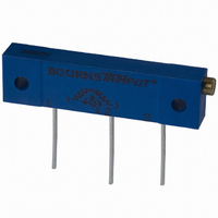
3059Y-1-500LF
Description
TRIMPOT 50 OHM 1.25"REC CER MT
Manufacturer
Bourns Inc.
Series
3059 - Sealedr
Specifications of 3059Y-1-500LF
Temperature Coefficient
±100ppm/°C
Resistance (ohms)
50
Termination Style
PC Pin
Power (watts)
1W
Tolerance
±10%
Number Of Turns
22
Adjustment Type
Side Adjustment
Resistive Material
Cermet
Mounting Type
Chassis Mount
Package / Case
Rectangular - 1.250" L x 0.190" W x 0.315" H (31.75mm x 4.83mm x 8.00mm)
Track Resistance
50ohm
No. Of Turns
22
Resistance Tolerance
± 10%
Power Rating
1W
Potentiometer Mounting
Through Hole
Resistance
50 Ohms
Operating Temperature Range
- 55 C to + 150 C
Element Type
Cermet
Dimensions
6.10 mm W x 31.75 mm L
Product
Trimmers
Taper
Linear
Rohs Compliant
Yes
Lead Free Status / RoHS Status
Lead free / RoHS Compliant
Lead Free Status / RoHS Status
Lead free / RoHS Compliant, Lead free / RoHS Compliant


Electrical Life
Rating.................................DC 12 V 50 mA
Contact Resistance .....100 milliohms max.
Insulation Resistance
Dielectric Strength...250 V AC for 1 minute
Contact Arrangement.......1 pole 1 position
Operation Force......................260 g ±50 g,
Stop Strength ..........Place the switch such
Stroke
Temperature Range..........-20 °C to +70 °C
Vibration Test........................Mil-STD-202F,
Shock Test ..........................MIL-STD-202F,
Cover Materials...................................Steel
Base Materials .....UL94V-0 PBT plus glass
Cover/Base Color...............................Black
Actuator Materials ................Dulacon POM
Actuator Color ...............Black, brown, red
Contact Disc Materials ....Phosphor bronze
Terminal Materials
Wave Soldering Process
Hand Soldering Process
Packaging .................1,000 pieces per bag
Specifications are subject to change without notice.
†
Customers should verify actual device performance in
their specific applications.
134
RoHS Directive 2002/95/EC Jan 27 2003 including Annex.
Electrical Characteristics
Environmental Characteristics
Physical Characteristics
..................500,000 cycles min. for 260 g
6mm type ...................0.25 +0.2/-0.1 mm
12mm type .........................0.35 ±0.1 mm
Frequency .............10-55-10 Hz/1 minute
Directions ................X,Y,Z, three mutually
Time.....................2 hours each direction.
Gravity ..........50 G (peak value), 11 msec
Direction & Times ..................6 sides and
.................100 megohms, DC 500 V min.
..............Use a soldering iron of 30 watts
........................Brass with silver cladding
.........Recommended solder temperature
that vertical, a static load of 3 kg shall
1,000,000 cycles min. for 100 g, 160g
be applied in the direction of actuator
or less, controlled at 320 °C (608 °F)
at 260 °C (500 °F) max., 5 seconds
for approximately 2 seconds while
operation for a period of 15 sec.
Method 213B, Condition A
plus glass fiber reinforced
160 g ±50 g, 100 g ±50 g
3 times in each direction.
perpendicular directions
with silver cladding
applying solder
fiber reinforced
High reliability
High reliability
Method 201A
REV 09/04
SDT Series – Tact Switch
Features
I
I
I
(.028)
DIMENSIONS: MM/(INCHES)
SDTX-644/648
RECOMMENDED PCB LAYOUT
CIRCUIT DIAGRAM
SDTX-610/620/630/650/660
0.70
Product Dimensions
Available sharp click feel with a
positive tactile feedback
Ultra-miniature and lightweight
structure suitable for high density
mounting
Economical with high reliability
A
B
(.256 ±.004)
(.071)
(.020)
0.50
1.80
6.5 ±0.1
T 1
T 3
C L
MAX.
T 1
T 3
(.311 ± .020)
(.256 ± .020)
7.90 ± 0.50
6.50 ± 0.50
(.039 ±.002)
(.012)
1.0 ±0.05
4 PLCS.
(.169)
0.30
4.30
C L
15°
C L
Dim.
Dim.
A
B
A
B
DIA
(.138)
3.50
C L
(.236)
T 4
6.0
T 2
(.177 ±.004)
(.138)
SDTX-644
SDTX-648
T 2
T 4
3.50
(.094 +.004/-0)
(.063 +.004/-0)
(.110 +.004/-0)
(.079 +.004/-0)
DIA.
4.5 ±0.1
(.177 ± .008)
2.4 +.1/-0
1.6 +.1/-0
2.8 +.1/-0
2.0 +.1/-0
4.50 ± 0.20
mm/(in)
mm/(in)
(.138 ± .020)
3.50 ± 0.50
(H ± .008)
H ± 0.20
I
I
SDTG-610/620/630/650/660
(.161)
CIRCUIT DIAGRAM
RECOMMENDED PCB LAYOUT
SDTG-644/648
4.10
(.028)
0.70
Insert molding in the contact with
special treatment prevents flux
buildup during soldering and permits
autodipping
RoHS compliant
(.016)
(.071)
0.40
B
1.80
A
(.256 ±.004)
6.5 ±0.1
(.161 ±.004)
T 4
T 2
4.1 ±0.1
MAX.
C L
T 4
T 2
(.012)
(.311 ± .020)
0.30
(.256 ± .020)
7.90 ± 0.50
6.50 ± 0.50
(.169)
4.30
C L
C L
15°
†
T 5
(.028)
0.70
T 5
Dim.
Dim.
(.138)
(.059)
3.50
1.50
B
B
A
A
C L
(.236)
6.0
T 3
T 1
(.177 ±.004)
SDTG-644
SDTG-648
T 3
T 1
DIA.
(.142)
3.60
(.094 +.004/-0)
(.063 +.004/-0)
(.110 +.004/-0)
(.079 +.004/-0)
4.5 ±0.1
(.039 ±.002)
(.177 ± .008)
(.138 ± .020)
2.4 +.1/-0
1.6 +.1/-0
2.8 +.1/-0
2.0 +.1/-0
4.50 ± 0.20
3.50 ± 0.50
1.0 ±0.05
mm/(in)
mm/(in)
(H ± .008)
5 PLCS.
H ± 0.20
DIA
Related parts for 3059Y-1-500LF
Image
Part Number
Description
Manufacturer
Datasheet
Request
R

Part Number:
Description:
POT 500K OHM 1-1/4" RECT CERM MT
Manufacturer:
Bourns Inc.
Datasheet:
Part Number:
Description:
POT 100 OHM 1-1/4" RECT CERM MT
Manufacturer:
Bourns Inc.
Datasheet:
Part Number:
Description:
POT 10K OHM 1-1/4" RECT CERM MT
Manufacturer:
Bourns Inc.
Datasheet:
Part Number:
Description:
POT 100K OHM 1-1/4" RECT CERM MT
Manufacturer:
Bourns Inc.
Datasheet:
Part Number:
Description:
POT 1.0K OHM 1-1/4" RECT CERM MT
Manufacturer:
Bourns Inc.
Datasheet:
Part Number:
Description:
POT 50K OHM 1-1/4" RECT CERM MT
Manufacturer:
Bourns Inc.
Datasheet:
Part Number:
Description:
POT 2.0K OHM 1-1/4" RECT CERM MT
Manufacturer:
Bourns Inc.
Datasheet:
Part Number:
Description:
POT 200K OHM 1-1/4" RECT CERM MT
Manufacturer:
Bourns Inc.
Datasheet:
Part Number:
Description:
POT 20K OHM 1-1/4" RECT CERM MT
Manufacturer:
Bourns Inc.
Datasheet:
Part Number:
Description:
POT 1.0M OHM 1-1/4" RECT CERM MT
Manufacturer:
Bourns Inc.
Datasheet:

Part Number:
Description:
Manufacturer:
Bourns, Inc.
Datasheet:
Part Number:
Description:
11mm Potentiometer
Manufacturer:
Bourns, Inc.
Datasheet: