3059Y-1-500LF Bourns Inc., 3059Y-1-500LF Datasheet - Page 64
3059Y-1-500LF
Manufacturer Part Number
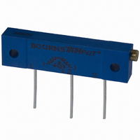
3059Y-1-500LF
Description
TRIMPOT 50 OHM 1.25"REC CER MT
Manufacturer
Bourns Inc.
Series
3059 - Sealedr
Specifications of 3059Y-1-500LF
Temperature Coefficient
±100ppm/°C
Resistance (ohms)
50
Termination Style
PC Pin
Power (watts)
1W
Tolerance
±10%
Number Of Turns
22
Adjustment Type
Side Adjustment
Resistive Material
Cermet
Mounting Type
Chassis Mount
Package / Case
Rectangular - 1.250" L x 0.190" W x 0.315" H (31.75mm x 4.83mm x 8.00mm)
Track Resistance
50ohm
No. Of Turns
22
Resistance Tolerance
± 10%
Power Rating
1W
Potentiometer Mounting
Through Hole
Resistance
50 Ohms
Operating Temperature Range
- 55 C to + 150 C
Element Type
Cermet
Dimensions
6.10 mm W x 31.75 mm L
Product
Trimmers
Taper
Linear
Rohs Compliant
Yes
Lead Free Status / RoHS Status
Lead free / RoHS Compliant
Lead Free Status / RoHS Status
Lead free / RoHS Compliant, Lead free / RoHS Compliant


Standard Resistance Range
Resistance Tolerance.........................±20 %
Contact Resistance Variation
Resolution ..........................................Infinite
Adjustment Angle .......................210 °± 15 ˚
Power Rating ..................................0.1 watt
Temperature Range ...........-10 °C to +70 °C
Temperature Coefficient ......±1,000 PPM/°C
Load Life .......................240 hours @ 50 °C
Torque (Operating) .................20~250 gf-cm
Stop Strength
Terminals .............................Solderable pins
Marking..............................Resistance code
Standard Packaging .........500 pcs. per bag
Specifications are subject to change without notice.
†
Customers should verify actual device performance in
their specific applications.
62
RoHS Directive 2002/95/EC Jan 27 2003 including Annex.
Electrical Characteristics
Environmental Characteristics
Physical Characteristics
...........................................100 " to 1 M"
Knob Side .................................800 gf-cm
Reverse Side .............................350 gf-cm
.................................................10 % max.
(see standard resistance table)
(+20/-5 % !TR)
REV 09/04
3318
6 mm Square Trimming Potentiometer
Features
I
I
I
Model 3318S
Recommended PCB Layout
DIMENSIONS: MM/(INCHES)
TOLERANCES: ±.25/(±.010) EXCEPT WHERE NOTED
Product Dimensions
Single-Turn / Carbon / Commercial
Open Frame
Cross slot rotor design suitable for
automatic adjustment equipment
Board retention features
(.099 ± .004)
(.079)
(.138)
(.134)
(.181 ± .01)
2.0
2.5 ± .10
3.5
(.067)
(.189)
(.032 ± .004)
3.4
4.6 ± .30
1.7
.800 ± .10
4.8
(.060)
(.047)
1.5
(.031)
(.150)
(.114)
(.043)
(.031)
1.2
0.8
.800
2.9
3.8
R
1.1
(.024)
1
.60
(.170)
(.197)
(.256)
104
4.3
5.0
6.5
2
(.040 ± .004)
(.197 ± .004)
1.0 ± .10
5.0 ± .10
(.138)
3 PLCS.
(.087)
3.5
(.112)
(.098)
3
2.2
0.3
2.5
(.031)
(.311± .001)
(.178)
(.138)
.800
DIA.
7.9 ± .03
4.5
3.5
(.122)
(.055)
3.1
1.4
DIA.
Mounting
Surface
(.067)
DIA.
1.7
I
I
I
I
Model 3318P
Recommended PCB Layout
Enclosed cover
PC board stand-offs
Adjustable front / back, top / bottom
RoHS compliant
(.134)
(.150)
CCW
3.4
3.8
(.032 ± .004)
.800 ± .10
(.197)
5.00
1
(.189)
4.8
(.060)
(.047)
3 PLCS.
1.5
1.2
(.079)
(.031)
.800
2.0
CLOCKWISE
1
(.197)
5.00
(.170)
(.197)
(.256)
4.3
104
5.0
†
6.5
2
2
(.063)
(.039 ± .004)
(.079 ± .004)
1.6
1.00 ± 0.10
2.00 ± 0.10
WIPER
(.062)
(.181 ± .012)
1.6
3
DIA.
4.6 ± .30
(.079)
(.250)
(.138)
6.35
3.5
2.0
R
(.138)
3.5
(.024)
(.122)
Mounting
Surface
0.6
DIA.
DIA.
DIA.
3.1
(.070)
3
1.8
(.040)
(.197)
(.040)
CW
1.0
5.0
1.0
Related parts for 3059Y-1-500LF
Image
Part Number
Description
Manufacturer
Datasheet
Request
R

Part Number:
Description:
POT 500K OHM 1-1/4" RECT CERM MT
Manufacturer:
Bourns Inc.
Datasheet:
Part Number:
Description:
POT 100 OHM 1-1/4" RECT CERM MT
Manufacturer:
Bourns Inc.
Datasheet:
Part Number:
Description:
POT 10K OHM 1-1/4" RECT CERM MT
Manufacturer:
Bourns Inc.
Datasheet:
Part Number:
Description:
POT 100K OHM 1-1/4" RECT CERM MT
Manufacturer:
Bourns Inc.
Datasheet:
Part Number:
Description:
POT 1.0K OHM 1-1/4" RECT CERM MT
Manufacturer:
Bourns Inc.
Datasheet:
Part Number:
Description:
POT 50K OHM 1-1/4" RECT CERM MT
Manufacturer:
Bourns Inc.
Datasheet:
Part Number:
Description:
POT 2.0K OHM 1-1/4" RECT CERM MT
Manufacturer:
Bourns Inc.
Datasheet:
Part Number:
Description:
POT 200K OHM 1-1/4" RECT CERM MT
Manufacturer:
Bourns Inc.
Datasheet:
Part Number:
Description:
POT 20K OHM 1-1/4" RECT CERM MT
Manufacturer:
Bourns Inc.
Datasheet:
Part Number:
Description:
POT 1.0M OHM 1-1/4" RECT CERM MT
Manufacturer:
Bourns Inc.
Datasheet:

Part Number:
Description:
Manufacturer:
Bourns, Inc.
Datasheet:
Part Number:
Description:
11mm Potentiometer
Manufacturer:
Bourns, Inc.
Datasheet: