3059Y-1-500LF Bourns Inc., 3059Y-1-500LF Datasheet - Page 42
3059Y-1-500LF
Manufacturer Part Number
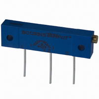
3059Y-1-500LF
Description
TRIMPOT 50 OHM 1.25"REC CER MT
Manufacturer
Bourns Inc.
Series
3059 - Sealedr
Specifications of 3059Y-1-500LF
Temperature Coefficient
±100ppm/°C
Resistance (ohms)
50
Termination Style
PC Pin
Power (watts)
1W
Tolerance
±10%
Number Of Turns
22
Adjustment Type
Side Adjustment
Resistive Material
Cermet
Mounting Type
Chassis Mount
Package / Case
Rectangular - 1.250" L x 0.190" W x 0.315" H (31.75mm x 4.83mm x 8.00mm)
Track Resistance
50ohm
No. Of Turns
22
Resistance Tolerance
± 10%
Power Rating
1W
Potentiometer Mounting
Through Hole
Resistance
50 Ohms
Operating Temperature Range
- 55 C to + 150 C
Element Type
Cermet
Dimensions
6.10 mm W x 31.75 mm L
Product
Trimmers
Taper
Linear
Rohs Compliant
Yes
Lead Free Status / RoHS Status
Lead free / RoHS Compliant
Lead Free Status / RoHS Status
Lead free / RoHS Compliant, Lead free / RoHS Compliant


Standard Resistance Range
Resistance Tolerance ................±10 % std.
Absolute Minimum Resistance
Contact Resistance Variation
Adjustability
Resolution.........................................Infinite
Insulation Resistance ....................500 vdc.
Dielectric Strength
Effective Travel......................12 turns nom.
Power Rating (300 volts max.)
Temperature Range........-65 °C to +150 °C
Temperature Coefficient ........±100 ppm/°C
Seal Test ...........................85 °C Fluorinert*
Humidity............MIL-STD-202 Method 106
Vibration ............30 G (1 % !TR; 1 % !VR)
Shock ..............100 G (1 % !TR; 1 % !VR)
Load Life....1,000 hours 0.25 watt @ 85 °C
Rotational Life............................200 cycles
Torque .................................3.0 oz-in. max.
Mechanical Stops .....................Wiper idles
Terminals ............................Solderable pins
Weight ..........................................0.015 oz.
Marking ...............................Manufacturer’s
Standard Packaging .........50 pcs. per tube
Adjustment Tool ..................................H-90
Wiper....................50 % (Actual TR) ±10 %
*”Fluorinert” is a registered trademark of 3M Co.
†
Specifications are subject to change without notice.
Customers should verify actual device performance in
their specific applications.
40
RoHS Directive 2002/95/EC Jan 27 2003 including Annex.
Electrical Characteristics
Environmental Characteristics
Physical Characteristics
Voltage........................................±0.02 %
Resistance ..................................±0.05 %
Sea Level .....................................600 vac
80,000 Feet..................................250 vac
85 °C .........................................0.25 watt
150 °C ............................................0 watt
.............................10 ohms to 1 megohm
................................1 % or 2 ohms max.
.............................3.0 % or 3 ohms max.
(see standard resistance table)
(2 % !TR; IR 100 Megohms)
trademark, resistance code,
wiring diagram, date code,
(closer tolerance available)
(2 % !TR; 3 % or 3 ohms,
whichever is greater, CRV)
whichever is greater, CRV)
(3 % !TR; 3 % or 3 ohms
manufacturer’s model
(whichever is greater)
(whichever is greater)
1,000 megohms min.
number and style
REV 09/04
3269
1/4 ˝ Square SMD Trimming Potentiometer
Features
I
I
I
3269P
Common Dimensions
DIMENSIONS: MM/(INCHES)
TOLERANCES: ±.25/(±.010) EXCEPT WHERE NOTED
Product Dimensions
(.293)
3269W
3269X
3269P
Common Dimensions
7.44
(.040)
1.02
(.205)
(.060 ± .015)
(.100)
3 PLCS.
5.21
2.54
Stable, infinite resolution cermet
element
Vertical and horizontal adjust styles
Optional packaging on
embossed tape
(.090)
TYP.
1.52 ± .38
2.29
3
CCW
ADJ. SLOT
(.018 ± .001)
2
1
.46 ± .03
DIA. TYP.
1
CLOCKWISE
2
(.070)
(.040)
1.78
1.02
(.100)
(.250 ± .020)
2.54
6.35 ± .51
1
3
(.040)
(.017 ± .002)
1.02
(.060 ± .015)
DIA.
(.040)
(.040)
1.02
(.060 ± .015)
1.52 ± .38
DIA. TYP.
1.02
2
.43 ± .05
1.52 ± .38
X
WIPER
(.250 ± .020)
(.020)
6.35 ± .51
.51
(.100) TYP. 3 PLCS.
2.54
SQ.
3
WIDE
(.170)
4.32
2.29
(.09)
3
X
2
(.020)
CW
3 PLCS.
.51
TYP.
1
3 PLCS.
(.293)
(.040)
7.44
1.02
DEEP
TYP
(.100)
(.040)
(.100)
2.54
1.02
2.54
TYP
I
I
RECOMMENDED PCB
LAYOUT – “P”
Popular distribution resistance values listed in boldface.
Special resistances available.
Model
Style
Standard or Modified
Product Indicator
Resistance Code
Embossed Tape Designator
Terminations
(.100)
(.100)
Standard Resistance Table
How To Order
2.54
2.54
RECOMMENDED PCB
LAYOUT - "P"
Blank = 90 % Tin / 10 % Lead-plated
Ohms
10
20
50
100
200
500
1,000
2,000
5,000
For P pin style:
For W & X pin styles:
For P, W & X pin styles:
Compatible with surface mount
manufacturing processes
RoHS compliant
processing information on lead free
surface mount trimmers
-11 = ±5 % TR
LF = 100 % Tin-plated (RoHS compliant)
-1 = Terminals away from
-2 = Terminals toward
-1 = Terminals toward
-2 = Terminals away from
(.047)
Resistance
1.19
G = Embossed Tape
TYP.
sprocket holes
sprocket holes
sprocket holes
sprocket holes
“P” Style – 750 pcs./13 ˝ reel
“W, X” Style – 500 pcs./13 ˝ reel
(Standard)
Code
(.382)
100
200
500
101
201
501
102
202
502
9.70
3269 X - 1 - 103 G LF
(.130)
3.30
TYP.
†
- see page 155 for
Ohms
10,000
20,000
25,000
50,000
100,000
200,000
250,000
500,000
1,000,000
RECOMMENDED PCB
RECOMMENDED PCB
LAYOUT – “W” & “X”
LAYOUT - "W" & "X"
(.300)
7.62
Resistance
(.100)
2.54
(.047)
1.19
Code
103
203
253
503
104
204
254
504
105
TYP.
(.100)
2.54
(.110)
2.79
TYP.
Related parts for 3059Y-1-500LF
Image
Part Number
Description
Manufacturer
Datasheet
Request
R

Part Number:
Description:
POT 500K OHM 1-1/4" RECT CERM MT
Manufacturer:
Bourns Inc.
Datasheet:
Part Number:
Description:
POT 100 OHM 1-1/4" RECT CERM MT
Manufacturer:
Bourns Inc.
Datasheet:
Part Number:
Description:
POT 10K OHM 1-1/4" RECT CERM MT
Manufacturer:
Bourns Inc.
Datasheet:
Part Number:
Description:
POT 100K OHM 1-1/4" RECT CERM MT
Manufacturer:
Bourns Inc.
Datasheet:
Part Number:
Description:
POT 1.0K OHM 1-1/4" RECT CERM MT
Manufacturer:
Bourns Inc.
Datasheet:
Part Number:
Description:
POT 50K OHM 1-1/4" RECT CERM MT
Manufacturer:
Bourns Inc.
Datasheet:
Part Number:
Description:
POT 2.0K OHM 1-1/4" RECT CERM MT
Manufacturer:
Bourns Inc.
Datasheet:
Part Number:
Description:
POT 200K OHM 1-1/4" RECT CERM MT
Manufacturer:
Bourns Inc.
Datasheet:
Part Number:
Description:
POT 20K OHM 1-1/4" RECT CERM MT
Manufacturer:
Bourns Inc.
Datasheet:
Part Number:
Description:
POT 1.0M OHM 1-1/4" RECT CERM MT
Manufacturer:
Bourns Inc.
Datasheet:

Part Number:
Description:
Manufacturer:
Bourns, Inc.
Datasheet:
Part Number:
Description:
11mm Potentiometer
Manufacturer:
Bourns, Inc.
Datasheet: