3059Y-1-500LF Bourns Inc., 3059Y-1-500LF Datasheet - Page 151
3059Y-1-500LF
Manufacturer Part Number
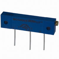
3059Y-1-500LF
Description
TRIMPOT 50 OHM 1.25"REC CER MT
Manufacturer
Bourns Inc.
Series
3059 - Sealedr
Specifications of 3059Y-1-500LF
Temperature Coefficient
±100ppm/°C
Resistance (ohms)
50
Termination Style
PC Pin
Power (watts)
1W
Tolerance
±10%
Number Of Turns
22
Adjustment Type
Side Adjustment
Resistive Material
Cermet
Mounting Type
Chassis Mount
Package / Case
Rectangular - 1.250" L x 0.190" W x 0.315" H (31.75mm x 4.83mm x 8.00mm)
Track Resistance
50ohm
No. Of Turns
22
Resistance Tolerance
± 10%
Power Rating
1W
Potentiometer Mounting
Through Hole
Resistance
50 Ohms
Operating Temperature Range
- 55 C to + 150 C
Element Type
Cermet
Dimensions
6.10 mm W x 31.75 mm L
Product
Trimmers
Taper
Linear
Rohs Compliant
Yes
Lead Free Status / RoHS Status
Lead free / RoHS Compliant
Lead Free Status / RoHS Status
Lead free / RoHS Compliant, Lead free / RoHS Compliant


Applications/Processing Guide – Standard and Lead Free
Trimming Potentiometers and Definitions
The following terms and definitions have been edited from the
Industrial Standard published by the Variable Electronics
Components Institute. It is intended to encourage
standardization in communication and understanding between
the manufacturer and user. The complete standard, including
detailed test procedures, is available upon request.
General Terms
TRIMMING POTENTIOMETER: An electrical mechanical
WIREWOUND TRIMMING POTENTIOMETER: A trimming
NON-WIREWOUND TRIMMING POTENTIOMETER:
RESISTANCE ELEMENT: A continuous, unbroken length of
ADJUSTMENT SHAFT: The mechanical input member of a
SINGLE-TURN ADJUSTMENT: Requires 360 ° or less
MULTITURN ADJUSTMENT: Requires more than 360 °
TERMINAL: An external member that provides electrical access
LEADWIRE TYPE TERMINAL: Flexible insulated conductor.
PRINTED CIRCUIT TERMINAL: Rigid uninsulated electrical
device with three terminals. Two terminals are connected to
the ends of a resistive element and one terminal is connected
to a movable conductive contact which slides over the
element, thus allowing the input voltage to be divided as a
function of the mechanical input. It can function as either a
voltage divider or rheostat.
potentiometer characterized by a resistance element made up
of turns of wire on which the wiper contacts only a small
portion of each turn.
A trimming potentiometer characterized by the continuous
nature of the surface area of the resistance element to be
contacted. Contact is maintained over a continuous, unbroken
path. The resistance is achieved by using material
compositions other than wire such as carbon, conductive
plastics, metal film and cermet.
resistive material without joints, bonds or welds except at the
junction of the element and the electrical terminals connected
to each end of the element, or at an intermediate point such as
a center tap.
trimming potentiometer which when actuated causes the
wiper to traverse the resistance element resulting in a change
in output voltage or resistance.
mechanical input to cause the wiper to traverse the total
resistance element.
mechanical adjustment to cause the wiper to traverse the total
resistance element.
to the resistance element and wiper.
conductor, suitable for printed circuit board plug-in.
SOLDER LUG TERMINAL: Rigid uninsulated electrical
WIPER: The wiper is the member in contact with the resistive
STOP-CLUTCH: A device which allows the wiper to idle at the
STOP – SOLID: A positive limit to mechanical and/or electrical
STACKING: The mounting of one trimming potentiometer
THEORETICAL RESOLUTION: (Wirewound only) The
Input and Output Terms
TOTAL APPLIED VOLTAGE: The total voltage applied between
OUTPUT VOLTAGE: The voltage between the wiper terminal
OUTPUT RATIO: The ratio of the output voltage to the
LOAD RESISTANCE: An external resistance as seen by the
Adjustment Terms
DIRECTION OF TRAVEL: Clockwise (CW) or counterclockwise
MECHANICAL TRAVEL — SOLID STOPS: The total travel of
conductor, suitable for external lead attachment.
element that allows the output to be varied when the
adjustment shaft is rotated.
ends of the resistive element without damage as the
adjustment shaft continues to be actuated in the same
direction.
adjustment.
adjacent to or on top of another utilizing the same mounting
hardware.
theoretical measurement of sensitivity to which the output
ratio may be adjusted; the reciprocal of the number of turns
of wire in resistance winding expressed as a percentage.
N = Total number of resistance wire turns.
N x 100 = Theoretical resolution percent.
the designated input terminals.
and the designated reference point. Unless otherwise
specified, the designated reference point is the CCW terminal.
designated input reference voltage. Unless otherwise specified,
the reference voltage is the total applied voltage.
Output Voltage (connected between the wiper terminal and
the designated reference point.)
(CCW) rotation when viewing the adjustment end of the
potentiometer.
1
YELLOW
CCW
1
CLOCKWISE
RED
2
WIPER
3
GREEN
CW
149
Related parts for 3059Y-1-500LF
Image
Part Number
Description
Manufacturer
Datasheet
Request
R

Part Number:
Description:
POT 500K OHM 1-1/4" RECT CERM MT
Manufacturer:
Bourns Inc.
Datasheet:
Part Number:
Description:
POT 100 OHM 1-1/4" RECT CERM MT
Manufacturer:
Bourns Inc.
Datasheet:
Part Number:
Description:
POT 10K OHM 1-1/4" RECT CERM MT
Manufacturer:
Bourns Inc.
Datasheet:
Part Number:
Description:
POT 100K OHM 1-1/4" RECT CERM MT
Manufacturer:
Bourns Inc.
Datasheet:
Part Number:
Description:
POT 1.0K OHM 1-1/4" RECT CERM MT
Manufacturer:
Bourns Inc.
Datasheet:
Part Number:
Description:
POT 50K OHM 1-1/4" RECT CERM MT
Manufacturer:
Bourns Inc.
Datasheet:
Part Number:
Description:
POT 2.0K OHM 1-1/4" RECT CERM MT
Manufacturer:
Bourns Inc.
Datasheet:
Part Number:
Description:
POT 200K OHM 1-1/4" RECT CERM MT
Manufacturer:
Bourns Inc.
Datasheet:
Part Number:
Description:
POT 20K OHM 1-1/4" RECT CERM MT
Manufacturer:
Bourns Inc.
Datasheet:
Part Number:
Description:
POT 1.0M OHM 1-1/4" RECT CERM MT
Manufacturer:
Bourns Inc.
Datasheet:

Part Number:
Description:
Manufacturer:
Bourns, Inc.
Datasheet:
Part Number:
Description:
11mm Potentiometer
Manufacturer:
Bourns, Inc.
Datasheet: