80.91.0.240.0000 FINDER, 80.91.0.240.0000 Datasheet - Page 126
80.91.0.240.0000
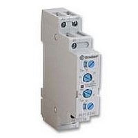
Manufacturer Part Number
80.91.0.240.0000
Description
TIMER, MULTIFUNCTION
Manufacturer
FINDER
Datasheet
1.81.01.0.230.0000.pdf
(165 pages)
Specifications of 80.91.0.240.0000
Contact Configuration
SPCO
Nom Input Voltage
240V
Delay Time Range
0.1s To 20h
Adjustment Type
Screwdriver Slot
Relay Mounting
DIN Rail
Svhc
No SVHC (15-Dec-2010)
Coil Voltage Vac Nom
240V
Coil Voltage Max
240V


87
124
L/+
L/+
N/–
L/+
N/–
L/+
* A voltage other than the
FUNCTIONS
Wiring diagram
Multi-function
without signal START
with signal START
N/–
** Type 87.02: regulated
NB.: remove link between
Z1-Z2 and position the Timer potentiometer on “zero”.
* 25-26-28 only for type 87.02 with 2 timed contacts. 21-22-24 only for type 87.02 with 1 instantaneous contact + 1 timed positioning the front DIP
switch. ** The LED on types 87.61 and 87.62 is illuminated when supply voltage is supplied to timer.
Without signal Start= Start via contact in supply line (A1). With signal Start = Start via contact into control terminal (B1).
A2
N/–
A2
A1
A2
U = Supply Voltage
S = Signal switch
C = Output Contact
A2
A1
A1
A1
supply voltage can be
applied to the command
START (B1).
Example:
A1 - A2 = 230 V AC/
B1 - A2 = 24 V AC
using an external
potentiometer
(10 k
Z1 Z2
Z1 Z2
B1
B1
B1
*
S
**
*
**
18
S
18
15
15
18
18
- 0.25 W).
15
87.01
16
87.02
15
87.01
87.02
16
16
16
(24
28
(24
28
(21)
25
(21)
25
26
22)
26
22)
87.01
87.02
Type
ON
OFF
U
C
U
S
C
U
C
U
C
U
C
U
S
C
U
C
U
S
C
U
C
U
S
C
LED**
Green
T
T
T
T
T
T
T
T
T
T
t<T T
T
In progress
In progress
T
T
Timing
None
None
0.5s
t<T
T
t>T
T
87 Series - Modular Timers 5 - 8 A
t<T
t<T
t<T
t<T
t<T
t<T
NO output
contact
Closed
Closed
Open
Open
(SW)
Apply power to timer. Output contacts transfer immediately and
cycle between ON and OFF for as long as power is applied.
The ratio is 1:1 (time on = time off).
(BE)
Power is permenently applied to the timer.
The output contacts transfer immediately on closure of the Signal
Switch (S). Opening the Signal Switch initiates the preset delay,
after which time the output contacts reset.
(DE)
Power is permenently applied to the timer.
On momentary or maintained closure of Signal Switch (S),
the output contacts transfer, and remain so for the duration of
the preset delay, after which they reset.
(EE)
Power is permenently applied to the timer.
On opening of the Signal Switch (S) the output contacts transfer,
and remain so for the duration of the preset delay, after which
they reset.
(AI)
Apply power to timer. Output contacts transfer after preset time
has elapsed. Reset occurs when power is removed.
(DI)
Apply power to timer. Output contacts transfer immediately.
After the preset time has elapsed, contacts reset.
(GI)
Apply power to timer. Output contacts transfer after preset time
has elapsed. Reset occurs after a fixed time of 0.5s. 0.5s.
(CE)
Power is permenently applied to the timer.
Closing the Signal Switch (S) initiates the preset delay, after
which time the output contacts transfer. Opening the Signal
switch initiates the same preset delay, after which time the output
contacts reset.
Permanently ON.
Selecting the function ON when power is applied to the relay
the first contact transfers immediately and remains in that position.
Permanently OFF.
The contact returns to the original position when the OFF function
is selected.
ON delay.
ON pulse.
Signal OFF pulse.
Fixed pulse (0.5s) delayed.
Signal OFF delay.
Signal ON and OFF delay.
Signal ON pulse.
Symmetrical recycler: ON start.
15 - 18
25 - 28*
15 - 16
25 - 26*
15 - 16
25 - 26*
15 - 18
25 -28*
Open
Timed
15 - 16
25 - 26*
15 - 18
25 - 28*
15 - 18
25 - 28*
Closed
15 - 16
25 - 26*
DIP switch
Contacts
Down
Up
21 - 24*
21 - 22*
21 - 22*
21 - 22*
Open
Instantaneous*
21 - 22*
21 - 24*
21 - 24*
21 - 24*
Closed
Related parts for 80.91.0.240.0000
Image
Part Number
Description
Manufacturer
Datasheet
Request
R

Part Number:
Description:
JUMPER LINK, 20WAY
Manufacturer:
FINDER
Datasheet:


Part Number:
Description:
INTERFACE RELAY, SPDT-CO, 24VAC/DC
Manufacturer:
FINDER
Datasheet:
Part Number:
Description:
INTERFACE RELAY, SPDT-CO, 24VDC
Manufacturer:
FINDER
Datasheet:

Part Number:
Description:
RELAY, SCREW TERM, 6A, 12VAC/DC
Manufacturer:
FINDER
Datasheet:
Part Number:
Description:
RELAY, SCREW TERM, 6A, 48VAC/DC
Manufacturer:
FINDER
Datasheet:
Part Number:
Description:
RELAY, SCREW TERM, 6A, 125VAC/DC
Manufacturer:
FINDER
Datasheet:
Part Number:
Description:
RELAY, SCREW TERM, 6A, 240VAC/DC
Manufacturer:
FINDER
Datasheet:
Part Number:
Description:
RELAY, SCREW TERM, 6A, 6VDC
Manufacturer:
FINDER
Datasheet:
Part Number:
Description:
RELAY, SCREW TERM, 6A, 12VDC
Manufacturer:
FINDER
Datasheet:
Part Number:
Description:
RELAY, SCRW TER, DPDT, 8A, 24VAC/DC
Manufacturer:
FINDER
Datasheet:
Part Number:
Description:
RELAY, SCREW TERM, DPDT, 8A, 12VDC
Manufacturer:
FINDER
Datasheet:
Part Number:
Description:
RELAY, SCREW TERM, DPDT, 8A, 24VDC
Manufacturer:
FINDER
Datasheet:

Part Number:
Description:
RELAY, SCREWLESS, 6A, 24VDC
Manufacturer:
FINDER
Datasheet: