80.91.0.240.0000 FINDER, 80.91.0.240.0000 Datasheet - Page 37
80.91.0.240.0000
Manufacturer Part Number
80.91.0.240.0000
Description
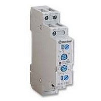
TIMER, MULTIFUNCTION
Manufacturer
FINDER
Datasheet
1.81.01.0.230.0000.pdf
(165 pages)
Specifications of 80.91.0.240.0000
Contact Configuration
SPCO
Nom Input Voltage
240V
Delay Time Range
0.1s To 20h
Adjustment Type
Screwdriver Slot
Relay Mounting
DIN Rail
Svhc
No SVHC (15-Dec-2010)
Coil Voltage Vac Nom
240V
Coil Voltage Max
240V


ORDERING INFORMATION
TECHNICAL DATA
INSULATION
OTHER DATA
CONTACT SPECIFICATIONS
F 45
Electrical life AC1 load (+85°C).
Example: a 45 series for P.C.B. relay + Faston 250, 1 NO contact, coil rated 12 V DC.
INSULATION according to EN 61810-5
VIBRATION RESISTANCE (10…55Hz): NO/NC
POWER LOST TO THE ENVIRONMENT
RECOMMENDED DISTANCE between RELAYS mounted on P.C.B.s mm
Series
Type
7 = P.C.B. - Faston 250
No. of poles
1 = 1 pole, 16 A
Coil version
7 = Sensitive DC
Coil voltage
see coil specifications
10
10
10
7
6
5
0
4 5
4
LOAD RATED CURRENT (A)
.
7
8
1
without contact current
.
7
12
with rated current
.
0 1 2
45 Series - Miniature P.C.B. Relays 16 A
A:
0 = Standard AgCdO
B:
3 = NO
4 = NC
16
Contact circuit
Contact material
g/g
W
W
.
insulation rated voltage
rated impulse withstand voltage
pollution degree
overvoltage category
10/10
0.4
1.8
≥5
0
A
H 45
Breaking capacity for DC1 load.
• When switching a resistive load (DC1) having voltage and
current values under the curve the expected electrical life is
≥ 100·10
• In case of DC13 loads the connection of a diode in parallel with
the load will permit the same electrical life as for a DC1 load.
Note: the release time of load will be increase.
3
B
0.2
0.1
20
10
6
4
2
1
20
3
0
C
cycles.
60
0
D
D:
0 = Flux proof (RT II)
C:
0 = None
Options
Special versions
DC VOLTAGE (V)
kV
100
V
250
3.6
3
III
140
180
220
35
45
Related parts for 80.91.0.240.0000
Image
Part Number
Description
Manufacturer
Datasheet
Request
R

Part Number:
Description:
JUMPER LINK, 20WAY
Manufacturer:
FINDER
Datasheet:


Part Number:
Description:
INTERFACE RELAY, SPDT-CO, 24VAC/DC
Manufacturer:
FINDER
Datasheet:
Part Number:
Description:
INTERFACE RELAY, SPDT-CO, 24VDC
Manufacturer:
FINDER
Datasheet:

Part Number:
Description:
RELAY, SCREW TERM, 6A, 12VAC/DC
Manufacturer:
FINDER
Datasheet:
Part Number:
Description:
RELAY, SCREW TERM, 6A, 48VAC/DC
Manufacturer:
FINDER
Datasheet:
Part Number:
Description:
RELAY, SCREW TERM, 6A, 125VAC/DC
Manufacturer:
FINDER
Datasheet:
Part Number:
Description:
RELAY, SCREW TERM, 6A, 240VAC/DC
Manufacturer:
FINDER
Datasheet:
Part Number:
Description:
RELAY, SCREW TERM, 6A, 6VDC
Manufacturer:
FINDER
Datasheet:
Part Number:
Description:
RELAY, SCREW TERM, 6A, 12VDC
Manufacturer:
FINDER
Datasheet:
Part Number:
Description:
RELAY, SCRW TER, DPDT, 8A, 24VAC/DC
Manufacturer:
FINDER
Datasheet:
Part Number:
Description:
RELAY, SCREW TERM, DPDT, 8A, 12VDC
Manufacturer:
FINDER
Datasheet:
Part Number:
Description:
RELAY, SCREW TERM, DPDT, 8A, 24VDC
Manufacturer:
FINDER
Datasheet:

Part Number:
Description:
RELAY, SCREWLESS, 6A, 24VDC
Manufacturer:
FINDER
Datasheet: