80.91.0.240.0000 FINDER, 80.91.0.240.0000 Datasheet - Page 160
80.91.0.240.0000
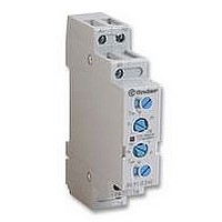
Manufacturer Part Number
80.91.0.240.0000
Description
TIMER, MULTIFUNCTION
Manufacturer
FINDER
Datasheet
1.81.01.0.230.0000.pdf
(165 pages)
Specifications of 80.91.0.240.0000
Contact Configuration
SPCO
Nom Input Voltage
240V
Delay Time Range
0.1s To 20h
Adjustment Type
Screwdriver Slot
Relay Mounting
DIN Rail
Svhc
No SVHC (15-Dec-2010)
Coil Voltage Vac Nom
240V
Coil Voltage Max
240V


158
i
GENERAL TECHNICAL DATA
CYCLE - Operate and subsequent release of a relay. Over a cycle the coil is energised and de-energised and the contact will progress from the point
at which it makes a circuit, through to breaking the circuit, to the point at which it re-makes the circuit.
PERIOD - The time covering one cycle.
DUTY FACTOR (DF) - During cyclic operation, DF is the ratio between the energised time and one period. For continuous duty, DF =1.
MECHANICAL LIFE - This test is performed by energising the coils of several relays at 8 cycles per second without any load applied to the con-
tacts. It establishes the ultimate durability of the relay where electrical wear of the contacts is not an issue. The maximum Electrical Life may therefore
approach the Mechanical Life where the electrical loading of the contacts is very small.
ELECTRICAL LIFE - See in CONTACT SPECIFICATIONS.
OPERATE TIME - The maximum operate time of contacts with the coil energised at rated voltage. In the catalogue, it includes the bounce time (see
following pattern).
RELEASE TIME - The maximum release time of contacts. In the catalogue, it includes the bounce time (see following pattern). It will increase if
protection modules are connected in parallel to the coil.
INSULATION COORDINATION according to EN 61810-5 - See in INSULATION DATA.
DIELECTRIC STRENGTH BETWEEN OPEN CONTACTS - See in INSULATION DATA.
AMBIENT TEMPERATURE RANGE - The range of temperatures of the immediate area where the relay is located, and for which operation of the
relay is guaranteed (under prescribed conditions).
ENVIRONMENTAL PROTECTION according to IEC 61810-7 - The relay technology categories describe the degree of sealing of the relay case:
Relay technology category
RT 0
RT I
RT II
RT III
RT IV
RT V
Hermetically sealed relay
Wash tight relay
Dust protected relay
Flux proof relay
Sealed relay
Unenclosed relay
U
0
N
t 1
t 2
t 3
t 4
: NC contact opening time at coil energization
: NO contact closing time (including conctact bounce) at coil energization (operate time)
: NO contact opening time at coil de-energization
: NC contact closing time (including contact bounce) at coil de-energization (release time)
Condition
Relay not provided with a protective case.
Relay provided with a case which protects its mechanism from dust.
Relay capable of being automatically soldered without allowing the migration of solder fluxes beyond
the intended areas.
Relay capable of being automatically soldered and subsequently undergoing a washing process to re
move flux residues without allowing the ingress of flux or washing solvents.
Relay provided with a case which has no venting to the outside atmosphere
Sealed relay having an enhanced level of sealing.
t 1
t 2
nominal voltage coil
position contact NO
position contact NC
GENERAL TECHNICAL INFORMATION
t 3
t 4
time
time
time
Related parts for 80.91.0.240.0000
Image
Part Number
Description
Manufacturer
Datasheet
Request
R

Part Number:
Description:
JUMPER LINK, 20WAY
Manufacturer:
FINDER
Datasheet:


Part Number:
Description:
INTERFACE RELAY, SPDT-CO, 24VAC/DC
Manufacturer:
FINDER
Datasheet:
Part Number:
Description:
INTERFACE RELAY, SPDT-CO, 24VDC
Manufacturer:
FINDER
Datasheet:

Part Number:
Description:
RELAY, SCREW TERM, 6A, 12VAC/DC
Manufacturer:
FINDER
Datasheet:
Part Number:
Description:
RELAY, SCREW TERM, 6A, 48VAC/DC
Manufacturer:
FINDER
Datasheet:
Part Number:
Description:
RELAY, SCREW TERM, 6A, 125VAC/DC
Manufacturer:
FINDER
Datasheet:
Part Number:
Description:
RELAY, SCREW TERM, 6A, 240VAC/DC
Manufacturer:
FINDER
Datasheet:
Part Number:
Description:
RELAY, SCREW TERM, 6A, 6VDC
Manufacturer:
FINDER
Datasheet:
Part Number:
Description:
RELAY, SCREW TERM, 6A, 12VDC
Manufacturer:
FINDER
Datasheet:
Part Number:
Description:
RELAY, SCRW TER, DPDT, 8A, 24VAC/DC
Manufacturer:
FINDER
Datasheet:
Part Number:
Description:
RELAY, SCREW TERM, DPDT, 8A, 12VDC
Manufacturer:
FINDER
Datasheet:
Part Number:
Description:
RELAY, SCREW TERM, DPDT, 8A, 24VDC
Manufacturer:
FINDER
Datasheet:

Part Number:
Description:
RELAY, SCREWLESS, 6A, 24VDC
Manufacturer:
FINDER
Datasheet: