80.91.0.240.0000 FINDER, 80.91.0.240.0000 Datasheet - Page 69
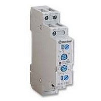
80.91.0.240.0000
Manufacturer Part Number
80.91.0.240.0000
Description
TIMER, MULTIFUNCTION
Manufacturer
FINDER
Datasheet
1.81.01.0.230.0000.pdf
(165 pages)
Specifications of 80.91.0.240.0000
Contact Configuration
SPCO
Nom Input Voltage
240V
Delay Time Range
0.1s To 20h
Adjustment Type
Screwdriver Slot
Relay Mounting
DIN Rail
Svhc
No SVHC (15-Dec-2010)
Coil Voltage Vac Nom
240V
Coil Voltage Max
240V


TECHNICAL DATA
INSULATION
IMMUNITY
OTHER DATA
CONTACT SPECIFICATIONS
Electrical life vs AC1 load.
H 62 (CO)
Breaking capacity for DC1 load.
A = Load applied to 1 contact.
B = Load applied to 2 contacts in series.
C = Load applied to 3 contacts in series.
• When switching a resistive load (DC1) having voltage and
current values under the curve the expected electrical life is
≥ 100·10
• In case of DC13 loads the connection of a diode in parallel with
the load will permit the same electrical life as for a DC1 load.
Note: the release time of load will be increase.
INSULATION according to EN 61810-5
VIBRATION RESISTANCE (10…55Hz): NO/NC
POWER LOST TO THE ENVIRONMENT
RECOMMENDED DISTANCE between RELAYS mounted on P.C.B.s mm
CONDUCTED DISTURBANCE IMMUNITY
10
10
10
0.2
0.1
20
10
6
4
2
1
7
6
5
20
0
3
cycles.
A
60
4
LOAD RATED CURRENT (A)
VOLTAGE DC (V)
100
B
8
C
140
without contact current
12
with rated current
180
LOCKABLE TEST BUTTON AND MECHANICAL FLAG INDICATOR (0040)
The dual-purpose Finder test button can be used in two ways:
Case 1) The plastic pip (located directly above the test button) remains intact. In this case, when the
test button is pushed, the contacts operate. When the test button is released the contacts return to their
former state.
Case 2) The plastic pip is broken-off (using an appropriate cutting tool). In this case, (in addition to
the above function), when the test button is pushed and rotated, the contacts are latched in the
operating state, and remain so until the test button is rotated back to its former position.
In both cases ensure that the test button actuation is swift and decisive.
220
16
g/g
F 62
W
W
insulation rated voltage
rated impulse withstand voltage
pollution degree
overvoltage category
BURST (according to EN 61000-4-4) level 4 (4 kV)
SURGE (according to EN 61000-4-5) level 4 (4kV)
5/3
2 CO
1.3
3.3
≥5
62 Series - Power Relays 16 A
H 62 (NO)
Breaking capacity for DC1 load.
A = Load applied to 1 contact.
B = Load applied to 2 contacts in series.
C = Load applied to 3 contacts in series.
• When switching a resistive load (DC1) having voltage and
current values under the curve the expected electrical life is
≥ 100·10
• In case of DC13 loads the connection of a diode in parallel with
the load will permit the same electrical life as for a DC1 load.
Note: the release time of load will be increase.
0.2
0.1
20
10
6
4
2
1
20
3 CO
1.3
4.3
3
cycles.
60
A
VOLTAGE DC (V)
kV
100
V
2 NO
3
5
400
4
3
III
140
B
C
3 NO
3
6
180
220
67
62
Related parts for 80.91.0.240.0000
Image
Part Number
Description
Manufacturer
Datasheet
Request
R

Part Number:
Description:
JUMPER LINK, 20WAY
Manufacturer:
FINDER
Datasheet:


Part Number:
Description:
INTERFACE RELAY, SPDT-CO, 24VAC/DC
Manufacturer:
FINDER
Datasheet:
Part Number:
Description:
INTERFACE RELAY, SPDT-CO, 24VDC
Manufacturer:
FINDER
Datasheet:

Part Number:
Description:
RELAY, SCREW TERM, 6A, 12VAC/DC
Manufacturer:
FINDER
Datasheet:
Part Number:
Description:
RELAY, SCREW TERM, 6A, 48VAC/DC
Manufacturer:
FINDER
Datasheet:
Part Number:
Description:
RELAY, SCREW TERM, 6A, 125VAC/DC
Manufacturer:
FINDER
Datasheet:
Part Number:
Description:
RELAY, SCREW TERM, 6A, 240VAC/DC
Manufacturer:
FINDER
Datasheet:
Part Number:
Description:
RELAY, SCREW TERM, 6A, 6VDC
Manufacturer:
FINDER
Datasheet:
Part Number:
Description:
RELAY, SCREW TERM, 6A, 12VDC
Manufacturer:
FINDER
Datasheet:
Part Number:
Description:
RELAY, SCRW TER, DPDT, 8A, 24VAC/DC
Manufacturer:
FINDER
Datasheet:
Part Number:
Description:
RELAY, SCREW TERM, DPDT, 8A, 12VDC
Manufacturer:
FINDER
Datasheet:
Part Number:
Description:
RELAY, SCREW TERM, DPDT, 8A, 24VDC
Manufacturer:
FINDER
Datasheet:

Part Number:
Description:
RELAY, SCREWLESS, 6A, 24VDC
Manufacturer:
FINDER
Datasheet: