80.91.0.240.0000 FINDER, 80.91.0.240.0000 Datasheet - Page 161
80.91.0.240.0000
Manufacturer Part Number
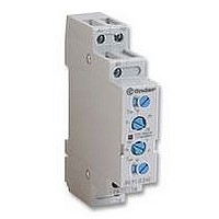
80.91.0.240.0000
Description
TIMER, MULTIFUNCTION
Manufacturer
FINDER
Datasheet
1.81.01.0.230.0000.pdf
(165 pages)
Specifications of 80.91.0.240.0000
Contact Configuration
SPCO
Nom Input Voltage
240V
Delay Time Range
0.1s To 20h
Adjustment Type
Screwdriver Slot
Relay Mounting
DIN Rail
Svhc
No SVHC (15-Dec-2010)
Coil Voltage Vac Nom
240V
Coil Voltage Max
240V


PROTECTION CATEGORY OF ENCLOSURES - according to EN 60529. The first digit is related to the protection against ingress of solid foreign
objects into the relay, and also against access to hazardous parts. The second digit relates to the protection against ingress of water. The IP grade
is related to normal use, in relay sockets or PC boards. For sockets, IP20 means that the socket is “finger-safe” (VDE0106).
Examples:
VIBRATION RESISTANCE - The maximum acceleration value (measured in g = 9.81 m/s
applied to the relay in any of the 3 axis, without the opening for more than 10 µs of the NO contact (if the coil is energised) or NC contact (if the
coil is not energised). In the energised state, the resistance is usually higher than in non-energised state.
POWER LOST TO THE ENVIRONMENT - The value of the power lost from the relay in working conditions (without contact load or at full load)
and may be used in the thermal design of panels.
MOUNTING POSITION - If not expressly indicated, any mounting position of the relay is permitted.
RECOMMENDED DISTANCE BETWEEN RELAYS MOUNTED ON PC.Boards - This is the minimum mounting distance suggested when
several relays are mounted on the same PC board. Care shall also be taken that other components mounted on the PC board do not heat the relays.
TORQUE - The maximum value of torque that can be used for tightening terminal screws, according to EN 60999, is 0.4 Nm for M2,5 screws, 0.5
Nm for M3 screws, 0.8 Nm for M3, 5 screws, 1.2 Nm for M4 screws.
The test torque is indicated in the catalogue.. Normally a 20% increase of this value is acceptable.
MAX WIRE SIZE - Maximum cross-section of cables (solid or stranded wire, without ferrules) that can be connected to each terminal. For use with
ferrules, the wire cross-section has to be reduced (e.g. from 4 to 2.5 mm
For any terminals, a minimum cross-section of 0.2 mm
According to EN 60204-1, it is permitted to introduce 2 or more wires into the same terminal. All Finder products are designed in such a way that
each terminal can accept 2 or more wires.
SPECIFIED TIME RANGE - Range in which it is possible to set timing using the time scales.
REPEATABILITY - The difference between the upper and lower limits of a range of values taken from several time measurements of a specified time
relay under identical stated conditions. Usually repeatability is indicated as a percentage of the mean value of all measured values.
RECOVERY TIME - The time necessary to start the relay again with the defined accuracy after the input energising quantity has been removed.
MINIMUM CONTROL IMPULSE - The shortest duration of a control impulse to fulfil and complete the time function.
SETTING ACCURACY - The difference between the measured value of the specified time and the reference value set on the scale.
THRESHOLD SETTING - For light-dependent relays this is the illumination level (measured in Lux) at which the relay will switch on or off. Pre-set
levels and the corresponding range of threshold that can be set using the regulator are indicated in the catalogue.
DELAY TIME - For light-dependent relays this is the delay between the change of state in the electronic circuit sensitive to light variation
(usually indicated by change of state of an LED) and the switching of the output relay contact.
CABLE GRIP - Specifies the range of the external diameter of cables that can be reliably gripped.
TYPE - For time switches, this is the type of program (weekly or daily).
PROGRAMS - For time switches, this is the number of different types of programs that can be stored.
MINIMUM INTERVAL SETTING - For time switches, this it is the minimum time interval that can be programmed.
BACK-UP POWER - The time when the switch won’t loose neither the programs nor the time.
MAXIMUM IMPULSE DURATION - For step relays and staircase switches, this is the maximum command pulse duration permitted.
MAX NO. OF ILLUMINATED PUSH-BUTTONS - For step relays and staircase switches, this is the maximum number of illuminated push-buttons
(having current absorption < 1mA @ 230 V AC) that can be connected without causing problems. If the push-button consumption is higher than 1
mA, the maximum number of push-buttons allowed is proportionally reduced (ie. 15 push-buttons x 1 mA is equivalent to 10 push-buttons x 1.5 mA).
IP 00 = Not protected.
IP 20 = Protected against solid foreign objects of 12.5 mm Ø and greater. Not protected against water.
IP 40 = Protected against solid foreign objects of 1 mm Ø and greater. Not protected against water.
IP 50 = Protected against powder (ingress of dust is not totally prevented, but dust shall not penetrate in a quantity to interfere with satisfactory
IP 67 = Totally protected against powder (dust-tight) and protected against the effect of temporary immersion in water.
Both slot-head and cross-head screwdrivers can be used.
operation of the relay). Not protected against water.
2
is allowed.
GENERAL TECHNICAL INFORMATION
2
, from 2.5 to 1.5 mm
2
) for frequencies in the range 10-55 Hz which can be
2
, from 1.5 to 1 mm
2
).
159
i
Related parts for 80.91.0.240.0000
Image
Part Number
Description
Manufacturer
Datasheet
Request
R

Part Number:
Description:
JUMPER LINK, 20WAY
Manufacturer:
FINDER
Datasheet:


Part Number:
Description:
INTERFACE RELAY, SPDT-CO, 24VAC/DC
Manufacturer:
FINDER
Datasheet:
Part Number:
Description:
INTERFACE RELAY, SPDT-CO, 24VDC
Manufacturer:
FINDER
Datasheet:

Part Number:
Description:
RELAY, SCREW TERM, 6A, 12VAC/DC
Manufacturer:
FINDER
Datasheet:
Part Number:
Description:
RELAY, SCREW TERM, 6A, 48VAC/DC
Manufacturer:
FINDER
Datasheet:
Part Number:
Description:
RELAY, SCREW TERM, 6A, 125VAC/DC
Manufacturer:
FINDER
Datasheet:
Part Number:
Description:
RELAY, SCREW TERM, 6A, 240VAC/DC
Manufacturer:
FINDER
Datasheet:
Part Number:
Description:
RELAY, SCREW TERM, 6A, 6VDC
Manufacturer:
FINDER
Datasheet:
Part Number:
Description:
RELAY, SCREW TERM, 6A, 12VDC
Manufacturer:
FINDER
Datasheet:
Part Number:
Description:
RELAY, SCRW TER, DPDT, 8A, 24VAC/DC
Manufacturer:
FINDER
Datasheet:
Part Number:
Description:
RELAY, SCREW TERM, DPDT, 8A, 12VDC
Manufacturer:
FINDER
Datasheet:
Part Number:
Description:
RELAY, SCREW TERM, DPDT, 8A, 24VDC
Manufacturer:
FINDER
Datasheet:

Part Number:
Description:
RELAY, SCREWLESS, 6A, 24VDC
Manufacturer:
FINDER
Datasheet: