80.91.0.240.0000 FINDER, 80.91.0.240.0000 Datasheet - Page 18
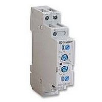
80.91.0.240.0000
Manufacturer Part Number
80.91.0.240.0000
Description
TIMER, MULTIFUNCTION
Manufacturer
FINDER
Datasheet
1.81.01.0.230.0000.pdf
(165 pages)
Specifications of 80.91.0.240.0000
Contact Configuration
SPCO
Nom Input Voltage
240V
Delay Time Range
0.1s To 20h
Adjustment Type
Screwdriver Slot
Relay Mounting
DIN Rail
Svhc
No SVHC (15-Dec-2010)
Coil Voltage Vac Nom
240V
Coil Voltage Max
240V


40
16
R 40 DC
U
U
R 40 AC
Wiring Diagram for 40 Series bistable coil version
Notes: The minimum SET or RESET impulse time is 20 ms. The maximum time can be continuous. In practice, always ensure that the SET and RESET
COIL SPECIFICATIONS
U
U
AC Operation
On momentary closure of the SET switch the relay is magnetised through
the diode and the relay contacts transfer to the set position and remain in
this position.
On momentary closure of the RESET switch the relay is demagnetised
through limiting resistor (R
reset position.
N
N
2.0
1.5
1.0
2.0
1.5
1.0
0.5
0.5
R
D = 1N4007
AC
-20
-20
contacts cannot be operated simultaneously.
~ 1.3 · R
V AC
0
0
AMBIENT TEMPERATURE (°C)
AMBIENT TEMPERATURE (°C)
DC
reset
20
set
20
AC
) and the contacts return to the
40
40
R
D
AC
40 Series - Miniature P.C.B. Relays 8 - 10 - 16 A
60
60
1
2
1
2
80
80
DC Operation
On momentary closure of the SET switch the relay is magnetised and the
relay contacts transfer to the set position and remain in this position.
On momentary closure of the RESET switch the relay is demagnetised
through limiting resistor (R
position.
V DC
Operating range vs ambient temperature.
1 - Max coil voltage permitted.
2 - Min pick-up voltage with coil at ambient temperature.
R 40 sens. DC
U
U
N
2.0
1.5
1.0
0.5
-20
set
AMBIENT TEMPERATURE (°C)
0
DC
reset
40.61
) and the contacts return to the reset
40.31/51/52
20
40
40.31/51/52
40.61
R
DC
60
2
1
80
Related parts for 80.91.0.240.0000
Image
Part Number
Description
Manufacturer
Datasheet
Request
R

Part Number:
Description:
JUMPER LINK, 20WAY
Manufacturer:
FINDER
Datasheet:


Part Number:
Description:
INTERFACE RELAY, SPDT-CO, 24VAC/DC
Manufacturer:
FINDER
Datasheet:
Part Number:
Description:
INTERFACE RELAY, SPDT-CO, 24VDC
Manufacturer:
FINDER
Datasheet:

Part Number:
Description:
RELAY, SCREW TERM, 6A, 12VAC/DC
Manufacturer:
FINDER
Datasheet:
Part Number:
Description:
RELAY, SCREW TERM, 6A, 48VAC/DC
Manufacturer:
FINDER
Datasheet:
Part Number:
Description:
RELAY, SCREW TERM, 6A, 125VAC/DC
Manufacturer:
FINDER
Datasheet:
Part Number:
Description:
RELAY, SCREW TERM, 6A, 240VAC/DC
Manufacturer:
FINDER
Datasheet:
Part Number:
Description:
RELAY, SCREW TERM, 6A, 6VDC
Manufacturer:
FINDER
Datasheet:
Part Number:
Description:
RELAY, SCREW TERM, 6A, 12VDC
Manufacturer:
FINDER
Datasheet:
Part Number:
Description:
RELAY, SCRW TER, DPDT, 8A, 24VAC/DC
Manufacturer:
FINDER
Datasheet:
Part Number:
Description:
RELAY, SCREW TERM, DPDT, 8A, 12VDC
Manufacturer:
FINDER
Datasheet:
Part Number:
Description:
RELAY, SCREW TERM, DPDT, 8A, 24VDC
Manufacturer:
FINDER
Datasheet:

Part Number:
Description:
RELAY, SCREWLESS, 6A, 24VDC
Manufacturer:
FINDER
Datasheet: