NZ1HS-2131-M EUCHNER, NZ1HS-2131-M Datasheet - Page 111
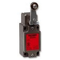
NZ1HS-2131-M
Manufacturer Part Number
NZ1HS-2131-M
Description
SAFETY SWITCH
Manufacturer
EUCHNER
Datasheet
1.NZ1HS-2131-M.pdf
(127 pages)
Specifications of NZ1HS-2131-M
Actuation Type
Lever
Operating Force Max
15N
Contact Voltage Ac Max
230V
Contact Voltage Dc Max
24V
Contact Current Ac Max
4A
Contact Current Dc Max
4A
Switch Terminals
Screw
Actuator Type
Lever Arm
Actuator Style
Lever


Appendix
SIL (Safety Integrity Level)
According to EN 61508 the objective for the probability of failure on the
execution of risk-reducing functions. The standard defines the require-
ments that are necessary to achieve a specific safety level (SIL).
Single-fault tolerance
Single-fault tolerance means that even after the occurrence of a single
failure, the agreed safe function continues to be provided.
Slow-action contact element
A slow-action contact element is characterized by the opening of the
switching element as a function of the speed at which the actuator is
moved.
Snap-action contact element
On snap-action contact elements the switching element jumps to the
other switch state from a defined actuator position. The movement of
the switching element is independent of the speed at which the actuator
is moved. Snap-action contact elements typically have hysteresis.
Standards
The European Machinery directive states that if harmonized standards
are observed, it is allowed to assume that the directive is met. Stan-
dards specify the requirements of the directive in more detail and as a
rule represent the general state-of-the-art . Manufacturers of safety
switches must comply with EN 60947 5. All EUCHNER safety switches
comply with this standard.
Start (automatic or manual)
An item of safety switchgear (e.g. safety relay ) can be started manually
or automatically. On a manual start, an enable signal is generated after
the Start button is pressed and a safe state has been detected. This
function is also termed static operation and is stipulated for emergency
stop devices (EN 60204-1).
On an automatic start, an enable signal is generated after a safe state
has been detected without any manual enable. This function is also
termed dynamic operation and is not allowed for emergency stop de-
vices (EN 60204-1).
Stop category
EN 60204-1 defines various stop categories; here stopping refers to
the shutdown of the machine.
Stop category 0 means that the machine is shutdown by the immediate
shutdown of the power.
Stop category 1 means that the machine is shutdown in a controlled
manner while the supply of power is maintained to bring the machine to
a standstill. Once standstill has been reached, the power is interrupted.
Stop category 2 means that the machine is shutdown in a controlled
manner while the supply of power is maintained to bring the machine to
a standstill. The power is not interrupted at standstill. This stop catego-
ry is not allowed to be used for shutdown in an emergency according to
EN 60204-1.
Switching elements
Switching elements are fitted in position switches. Switching elements
are available with a normally closed function, with a normally open function
and as positively driven contacts . EUCHNER supplies switching elements
with one, two, three and four contacts for the various switch types.
Switching elements can be slow-action contact elements or snap-
action contact elements .
Tampering
Tampering is the conscious disabling or bypassing of safety guards
and their components. Safety switches and other safety device must
be designed such that the protective function cannot be changed or
bypassed by hand or using one simple action. Simple actions include
using:
Actions that are not regarded as simple are actions that require more
than one work step with tools.
The inability to bypass by simple means (BGI 575) is:
It should be taken into account in the design that, despite safety guards,
straightforward and correct operation of machines and systems must
be possible. If this aspect is not taken into account, the probability of
bypassing safety measures will increase.
Testing
Testing is intended to ensure that a safety system functions correctly.
Testing can be performed automatically, by the control system, in the
form of monitoring or testing during the process. Depending on the
requirements, a combination of automatic and manual testing is also
possible. The testing must be repeated at defined intervals as a function
of the risk analysis. Testing is required for category 2 and 4 according
to EN 954 1 and should also be performed for category 3.
Switching
element 2
Switching
element 1
Screwdrivers
Ball-point pens
Nails
Pieces of wire
Adhesive tape
etc.
The dismantling of parts
The turning of the safety switch away from its protective position
The use of a second actuator
The bridging of the contacts
Guiding the actuator in a C rail
4 contact switching element
element 4
element 3
Switching
Switching
111
Related parts for NZ1HS-2131-M
Image
Part Number
Description
Manufacturer
Datasheet
Request
R

Part Number:
Description:
ACTUATOR
Manufacturer:
EUCHNER
Datasheet:

Part Number:
Description:
ACTUATOR
Manufacturer:
EUCHNER
Datasheet:

Part Number:
Description:
ACTUATOR
Manufacturer:
EUCHNER
Datasheet:

Part Number:
Description:
ACTUATOR
Manufacturer:
EUCHNER
Datasheet:

Part Number:
Description:
JOYSTICK SWITCH
Manufacturer:
EUCHNER
Datasheet:

Part Number:
Description:
JOYSTICK SWITCH
Manufacturer:
EUCHNER
Datasheet:

Part Number:
Description:
JOYSTICK SWITCH
Manufacturer:
EUCHNER
Datasheet:

Part Number:
Description:
JOYSTICK SWITCH
Manufacturer:
EUCHNER
Datasheet:

Part Number:
Description:
JOYSTICK SWITCH
Manufacturer:
EUCHNER
Datasheet:


Part Number:
Description:
LIMIT SWITCH, SINGLE
Manufacturer:
EUCHNER
Datasheet:

Part Number:
Description:
SAFETY SWITCH
Manufacturer:
EUCHNER
Datasheet:

Part Number:
Description:
SAFETY SWITCH
Manufacturer:
EUCHNER
Datasheet:

Part Number:
Description:
SAFETY SWITCH
Manufacturer:
EUCHNER
Datasheet:

Part Number:
Description:
SAFETY SWITCH
Manufacturer:
EUCHNER
Datasheet: