NZ1HS-2131-M EUCHNER, NZ1HS-2131-M Datasheet - Page 7
NZ1HS-2131-M
Manufacturer Part Number
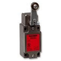
NZ1HS-2131-M
Description
SAFETY SWITCH
Manufacturer
EUCHNER
Datasheet
1.NZ1HS-2131-M.pdf
(127 pages)
Specifications of NZ1HS-2131-M
Actuation Type
Lever
Operating Force Max
15N
Contact Voltage Ac Max
230V
Contact Voltage Dc Max
24V
Contact Current Ac Max
4A
Contact Current Dc Max
4A
Switch Terminals
Screw
Actuator Type
Lever Arm
Actuator Style
Lever


General
Snap-action switching element
On snap-action switching elements, the change from the completely
closed state to the completely open state is made at a defined point. As
a result the switching point is at a defined position unlike on slow-action
contact elements. Snap-action switching elements typically have a
switching hysteresis.
Positively driven contacts
Positively driven contacts are used in the switching elements. These are
special switching elements that are designed to ensure that the switching
contacts are always reliably separated. Even if contacts are welded
together, the connection is opened by the actuating force.
It is a common feature of all switching elements that at least one switching
element is designed as a positively driven contact. Often two positively
driven contacts are employed to increase safety using the principle of
duplicated design (redundancy). This dual-channel design ensures that
on the failure of one channel or on a fault in the control circuit (e.g. in the
machine wiring), the interlocking can still be provided with the aid of the
second channel.
Door auxiliary contacts
In addition, door auxiliary contacts are also required to indicate to the
control system that the safety guard is open. As these switching elements
do not have any safety function, either normally closed or normally open
contacts can be used.
Protection against tampering
A safety switch can only ensure that operation is free of hazards if it is
not bypassed. To prevent tampering on switches with separate actuator,
the actuator should be positively mounted on the safety guard. All
actuating elements are supplied with safety screws that can be fastened
using commonly available tools, but that can only be undone with extre-
me difficulty. It should be ensured that the screws cannot be undone
with simple tools.
Increased protection against bypassing can be achieved by using a
covered installation. In this way it can be made more difficult to insert
replacement actuators, or this action can be prevented. Suitable for this
purpose, for instance, are rear wall mounting or guiding the actuator in
a C rail.
Switches with safety function can be installed covered so that the
actuating element cannot be reached.
Free position
End position
Snap-action switching element
Travel diagram
mm
0
1
2
3
4
5
6
Protective plate
On switches with separate actuator, increased protection against
bypassing can be achieved by using a protective plate over the switch
head. The switch head's rearward opening is then rendered almost
inaccessible.
Lockout bar
To prevent the unintentional closing of a safety guard, lockout bars are
available for switches with separate actuator. The lockout bar is inserted
in the safety switch instead of the actuator when the safety guard is
open. The lockout bar can then be secured with commercially available
padlocks (up to five locks) to protect against removal.
This feature guarantees protection for anyone (e.g. maintenance or
service personnel, or cleaning staff) who needs to enter potentially
hazardous areas. The switches cannot signal a safe (closed) state with
a lockout bar fitted. As a result unintentional starting of the machine is
not possible.
Safety switch with separate actuator with protective plate
Lockout bar for three padlocks
Guiding the actuator in a C rail
Protective
plate
7
Related parts for NZ1HS-2131-M
Image
Part Number
Description
Manufacturer
Datasheet
Request
R

Part Number:
Description:
ACTUATOR
Manufacturer:
EUCHNER
Datasheet:

Part Number:
Description:
ACTUATOR
Manufacturer:
EUCHNER
Datasheet:

Part Number:
Description:
ACTUATOR
Manufacturer:
EUCHNER
Datasheet:

Part Number:
Description:
ACTUATOR
Manufacturer:
EUCHNER
Datasheet:

Part Number:
Description:
JOYSTICK SWITCH
Manufacturer:
EUCHNER
Datasheet:

Part Number:
Description:
JOYSTICK SWITCH
Manufacturer:
EUCHNER
Datasheet:

Part Number:
Description:
JOYSTICK SWITCH
Manufacturer:
EUCHNER
Datasheet:

Part Number:
Description:
JOYSTICK SWITCH
Manufacturer:
EUCHNER
Datasheet:

Part Number:
Description:
JOYSTICK SWITCH
Manufacturer:
EUCHNER
Datasheet:


Part Number:
Description:
LIMIT SWITCH, SINGLE
Manufacturer:
EUCHNER
Datasheet:

Part Number:
Description:
SAFETY SWITCH
Manufacturer:
EUCHNER
Datasheet:

Part Number:
Description:
SAFETY SWITCH
Manufacturer:
EUCHNER
Datasheet:

Part Number:
Description:
SAFETY SWITCH
Manufacturer:
EUCHNER
Datasheet:

Part Number:
Description:
SAFETY SWITCH
Manufacturer:
EUCHNER
Datasheet: