NZ1HS-2131-M EUCHNER, NZ1HS-2131-M Datasheet - Page 66
NZ1HS-2131-M
Manufacturer Part Number
NZ1HS-2131-M
Description
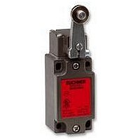
SAFETY SWITCH
Manufacturer
EUCHNER
Datasheet
1.NZ1HS-2131-M.pdf
(127 pages)
Specifications of NZ1HS-2131-M
Actuation Type
Lever
Operating Force Max
15N
Contact Voltage Ac Max
230V
Contact Voltage Dc Max
24V
Contact Current Ac Max
4A
Contact Current Dc Max
4A
Switch Terminals
Screw
Actuator Type
Lever Arm
Actuator Style
Lever


Safety Switches with Separate Actuator, Metal Housing
Safety switch TZ with guard locking and guard locking monitoring
Escape release
Is used for the manual release of the guard locking
from within the danger area without tools. The
disable can only be removed and the switch
returned to its operating state using a key included.
Solenoid operating voltage and LED function
display
The following voltage range is available:
Locking methods
TZ1 Closed-circuit current principle, locking by
TZ2 Open-circuit current principle, locking by
Switching elements (see also page 11)
SK For monitoring the door/actuator position
ÜK For monitoring the guard locking (built-in solenoid)
For combinations available see ordering table:
Ordering table
Series
66
2131H Slow-action contact element
3131H Slow-action contact element
TZ
Mechanical release on the front
Escape release from the rear with key
button
Two LEDs, red and green
Plug connector optionall
Actuating head fitted left or right
528H Slow-action contact element
24 V
spring force. Release by applying voltage
to the solenoid.
applying voltage to the solenoid. Release
by spring force.
Mechanical
Locking
Electrical
1 NC
3 NC
2 NC
AC/DC
1
2
+ 1 NO
+ 1 NO
+ 2 NO
Switch
head
Right
Right
-15%, +10%
Left
Left
LE
RE
LE
RE
SK: 2131H, 3 NC
SK: 2131H, 3 NC
SK: 528H, 1 NC
ÜK: 528H, 1 NC
SK: 2131H, 3 NC
ÜK: 3131H, 2 NC
SK: 528H, 1 NC
ÜK: 528H, 1 NC
ÜK: 3131H, 2 NC
SK: 528H, 1 NC
ÜK: 528H, 1 NC
SK: 2131H, 3 NC
ÜK: 3131H, 2 NC
SK: 528H, 1 NC
ÜK: 528H, 1 NC
ÜK: 3131H, 2 NC
Switching element
+ 1 NO
+ 1 NO
+ 1 NO
+ 1 NO
+ 1 NO
+ 1 NO
+ 1 NO
+ 1 NO
+ 1 NO
+ 2 NO
+ 1 NO
+ 2 NO
+ 1 NO
+ 2 NO
+ 1 NO
+ 2 NO
Cable entry M20 x 1.5
Dimension drawings
Wiring diagram
Cable entry
M20 x 1.5
Connection
31
PE
14
13
22
21
14
13
22
21
1
2
5
6
3
4
Metric
Metric
Metric
Metric
Metric
Metric
Metric
Metric
20
M
M
M
M
M
M
M
M
SK:528H/ÜK:528H
13
21
SK:528H
5
actuator inserted and locked
RD
61
Escape
release
14
22
GN
actuating head on left is a mirror image
(red key button)
(red key button)
(red key button)
(red key button)
(red key button)
(red key button)
(red key button)
(red key button)
Escape release
Escape release
Escape release
Escape release
Escape release
Escape release
Escape release
Escape release
13
21
ÜK:528H
Version
14
22
Mechanical
release
GN
35
RD
TZ1LE024MVAB-C1828
TZ1RE024MVAB-C1828
TZ2LE024MVAB-C1828
TZ2RE024MVAB-C1828
100
TZ1LE024M-C1815
TZ1RE024M-C1815
TZ2LE024M-C1815
TZ2RE024M-C1815
110
c
36
087 990
089 468
087 991
089 469
089 460
087 290
089 461
087 291
24 V
52
a
36
+4
18
±1
23
25
PE
12
11
22
21
34
33
42
41
14
13
22
21
34
33
42
41
2
5
6
3
4
1
SK:2131H/ÜK:3131H
Black cover
11
21
33
41
SK:2131H
RD
a Travel without operation:
actuator is in the guide slot,
however function is not triggered.
b Switching operation completed:
actuator must be inserted to this
point to ensure reliable switching.
The actuator must be withdrawn at
least to point a for switching off.
12
22
34
42
GN
Please order
actuator
separately (see
page 76)
TZ1LE110MVAB-C1828
TZ1RE110MVAB-C1828
13
33
21
41
ÜK:3131H
On request
On request
On request
On request
On request
On request
094 311
094 312
110 V
14
34
22
42
For cable glands
see page 82
Related parts for NZ1HS-2131-M
Image
Part Number
Description
Manufacturer
Datasheet
Request
R

Part Number:
Description:
ACTUATOR
Manufacturer:
EUCHNER
Datasheet:

Part Number:
Description:
ACTUATOR
Manufacturer:
EUCHNER
Datasheet:

Part Number:
Description:
ACTUATOR
Manufacturer:
EUCHNER
Datasheet:

Part Number:
Description:
ACTUATOR
Manufacturer:
EUCHNER
Datasheet:

Part Number:
Description:
JOYSTICK SWITCH
Manufacturer:
EUCHNER
Datasheet:

Part Number:
Description:
JOYSTICK SWITCH
Manufacturer:
EUCHNER
Datasheet:

Part Number:
Description:
JOYSTICK SWITCH
Manufacturer:
EUCHNER
Datasheet:

Part Number:
Description:
JOYSTICK SWITCH
Manufacturer:
EUCHNER
Datasheet:

Part Number:
Description:
JOYSTICK SWITCH
Manufacturer:
EUCHNER
Datasheet:


Part Number:
Description:
LIMIT SWITCH, SINGLE
Manufacturer:
EUCHNER
Datasheet:

Part Number:
Description:
SAFETY SWITCH
Manufacturer:
EUCHNER
Datasheet:

Part Number:
Description:
SAFETY SWITCH
Manufacturer:
EUCHNER
Datasheet:

Part Number:
Description:
SAFETY SWITCH
Manufacturer:
EUCHNER
Datasheet:

Part Number:
Description:
SAFETY SWITCH
Manufacturer:
EUCHNER
Datasheet: