NZ1HS-2131-M EUCHNER, NZ1HS-2131-M Datasheet - Page 8
NZ1HS-2131-M
Manufacturer Part Number
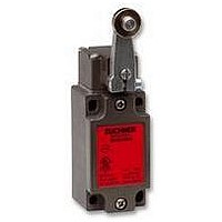
NZ1HS-2131-M
Description
SAFETY SWITCH
Manufacturer
EUCHNER
Datasheet
1.NZ1HS-2131-M.pdf
(127 pages)
Specifications of NZ1HS-2131-M
Actuation Type
Lever
Operating Force Max
15N
Contact Voltage Ac Max
230V
Contact Voltage Dc Max
24V
Contact Current Ac Max
4A
Contact Current Dc Max
4A
Switch Terminals
Screw
Actuator Type
Lever Arm
Actuator Style
Lever


General
Guard locking
Safety switches with separate actuator are available both with and without
guard locking. Guard locking is a feature that prevents the unintentional
opening of a door as long as there is a hazard. The door is locked by
preventing the removal of the actuator from the safety switch.
The series NZ.VZ.VS and TZ listed in this catalog are safety switches
with separate actuator with guard locking.
Protection of personnel
Guard locking is required if a hazard cannot be removed immediately by
shutting down a machine (e.g. a movement with overtravel). In this case
fail-safe control of the locking solenoid for the guard locking is required.
This requirement can, for instance, be achieved by a standstill monitor
or a safe delay. The safety switch must also provide a facility for
monitoring the position of the solenoid.
The series TZ has the guard locking monitoring necessary for this purpose
and can therefore be used for the protection of personnel.
Process protection
Often a safety guard is only to be locked to prevent interruption to the
process due to unintentional opening of the safety guard. In this case
the position of the interlocking solenoid does not need to be integrated
in the safety circuit. In this situation the series NZ.VZ.VS and TZ safety
switches are suitable.
Housing material
The series N1A, NB, NZ and TZ safety switches have a die-cast alloy
housing with an anodized surface. Due to the durable housing material
and the high degree of protection (up to IP 67), these switches can be
used even under the harshest conditions.
Attaching safety switches with safety function, with
separate actuator and the actuators
Certain requirements must be met on attaching the safety switches.
Any installation position can be used, however, the switches must be
attached such that their position cannot be changed in operation. On
the other hand, if necessary it must be possible to replace the switches
at any time without renewed adjustment.
These requirements are achieved by using reliable fixings that can only
be undone using tools. To prevent a change to the position, there must
also be no movement in the joint (e.g. by using dowel pins).
8
Safety switch
NZ.VZ.VS
Safety switch
TZ
The same applies to the trip dogs for switches with safety function. A
joint without movement is also required here. Above all else, loosening
must be prevented. In addition, it must be ensured that cams and trip
dogs can only be mounted in the correct position.
To prevent tampering, safety screws can also be used for the attachment
of safety switches and trip dogs.
Often the actuator approach direction does not match the standard
alignment of the actuating head as delivered. For this reason, the
actuating heads on the safety switches NZ and TZ can be very
straightforwardly adjusted to the required direction. In addition, the
actuating direction can be adjusted such that the actuator only switches
in one direction.
After undoing the four fastening screws, the actuating head can be rotated
in 90° steps. If for reasons of protection against tampering, renewed
removal of the actuating head is to be prevented, the actuating head
can be fastened to the basic housing using safety screws. You will find
appropriate fixings in the accessories section of this catalog.
Mounting plates are available to ease the attachment of switches with
separate actuator and also actuators. Bolts attached to the safety door
are extremely helpful. Using bolts all requirements, e.g. the mechanical
end stop for the door and the exact guidance of the actuator are optimally
met.
Position
yellow
yellow
white
white
Use
Pos.driven contacts
Pos.driven contacts
Pos.driven contacts
Active
One side left
NO contacts
NO contacts
NO contacts
left + right
Both sides
One side
Actuation
State
State
right
State
Attaching safety switches and actuators
End stop
closed
closed
closed
open
Left
Not activated
closed
closed
closed
open
open
open
closed
closed
closed
Right
open
white
yellow
Use
Related parts for NZ1HS-2131-M
Image
Part Number
Description
Manufacturer
Datasheet
Request
R

Part Number:
Description:
ACTUATOR
Manufacturer:
EUCHNER
Datasheet:

Part Number:
Description:
ACTUATOR
Manufacturer:
EUCHNER
Datasheet:

Part Number:
Description:
ACTUATOR
Manufacturer:
EUCHNER
Datasheet:

Part Number:
Description:
ACTUATOR
Manufacturer:
EUCHNER
Datasheet:

Part Number:
Description:
JOYSTICK SWITCH
Manufacturer:
EUCHNER
Datasheet:

Part Number:
Description:
JOYSTICK SWITCH
Manufacturer:
EUCHNER
Datasheet:

Part Number:
Description:
JOYSTICK SWITCH
Manufacturer:
EUCHNER
Datasheet:

Part Number:
Description:
JOYSTICK SWITCH
Manufacturer:
EUCHNER
Datasheet:

Part Number:
Description:
JOYSTICK SWITCH
Manufacturer:
EUCHNER
Datasheet:


Part Number:
Description:
LIMIT SWITCH, SINGLE
Manufacturer:
EUCHNER
Datasheet:

Part Number:
Description:
SAFETY SWITCH
Manufacturer:
EUCHNER
Datasheet:

Part Number:
Description:
SAFETY SWITCH
Manufacturer:
EUCHNER
Datasheet:

Part Number:
Description:
SAFETY SWITCH
Manufacturer:
EUCHNER
Datasheet:

Part Number:
Description:
SAFETY SWITCH
Manufacturer:
EUCHNER
Datasheet: