TMC SIXPACK 2 TRINAMIC, TMC SIXPACK 2 Datasheet - Page 10
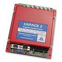
TMC SIXPACK 2
Manufacturer Part Number
TMC SIXPACK 2
Description
CONTROLLER, STEPPER MOTOR, AMPLIF
Manufacturer
TRINAMIC
Datasheet
1.TMC_SIXPACK_2.pdf
(48 pages)
Specifications of TMC SIXPACK 2
Supply Voltage Range
15Vdc To 48Vdc
No. Of Phases
Two
Output Current
1.4A
Approval Bodies
CE
Current Limit Max
1.4A
Current Limit Min
300mA
External Depth
35mm
External Length / Height
180mm
Svhc
No SVHC (15-Dec-2010)
Rohs Compliant
Yes
Lead Free Status / RoHS Status
Lead free / RoHS Compliant


SIXpack 2 – manual (V1.01 / May 5
5.2.3 Baudrate of serial interface
The baud rate of the serial interface is set via jumper JP1 and JP2 (refer Figure 5.1).
(*): The SIXpack 2 has an internal buffer for 16 CAN commands which need about 2ms execution time
each. This might limit the maximum data throughput.
The command GetInputValues (SQPack-Tab I/O, $30) provides the actual jumper configuration in the
variable AllInputs.
Bit 6 = Jumper1, Bit 7 = Jumper2
The baud rate for RS232/485 can be modified by software also. This setting is not stored permanently.
In order to get the actual jumper-configurations send CMD $30.
5.2.4 Termination of CAN/RS485
Each interface can be terminated by setting the jumpers “TERM CAN” and “TERM RS485” (refer Figure
5.1).
5.2.5 Seven-segment display
The seven segment display shows the number of active motors. With an appropriate power supply a “0”
is shown at start. The decimal point indicates that a reference search at any motor is accomplished.
If a malfunction occurs the display shows “8”, “C” or “F”. Try to restart the SIXpack 2.
5.2.6 Driver enable
The jumper “Driver enable” (close to the motor connectors) enables (jumper set) or disables (jumper
open) the drivers for all motors. If the drivers are disabled, i.e.. jumper open, it is safe to disconnect the
motors while power on and retain the actual settings of the SIXpack 2.
Hint: It is possible to use a switch to enable/disable the drivers.
Driver enable
Multifunctional
"RS232"
DIP-switches:
1: M2 I 1
2: M2 I 0
3: M1 I 1
4: M1 I 0
5: MD246
6: MD135
7: 2A_246
8: 2A_135
2
1
JP1 JP2
Figure 5.2: Driver enable, DIP switches and motor connectors
X
X
-
-
10
8
6
4
2
9
7
5
3
1
X
X
Table 5.1: Adjustment of baudrate with jumpers
-
-
SIXpack 2
1
2
3
4
5
6
7
8
Baud rate RS232/RS485
th
, 2006) 10
57600
38400
19200
9600
Motor connectors
1 Mbit/s (*)
500 kbit/s (*)
125 kbit/s (*)
250 kbit/s (default)(*)
Baud rate CAN
1
2
3
4
5
6
7
8
DIP-switches:
1: M6 I 1
2: M6 I 0
3: M5 I 1
4: M5 I 0
5: M4 I 1
6: M4 I 0
7: M3 I 1
8: M3 I 0
Related parts for TMC SIXPACK 2
Image
Part Number
Description
Manufacturer
Datasheet
Request
R

Part Number:
Description:
Alarm, Piezoelectric, 75 dBA to 95 dBA @ 2 Ft., Medium Loud Continuous, 30-120VAC
Manufacturer:
Floyd Bell Inc.
Part Number:
Description:
Alarm, Piezoelectric, 75 dBA to 95 dBA @ 2 Ft., Medium Loud Continuous, 9-48VDC
Manufacturer:
Floyd Bell Inc.
Part Number:
Description:
57mm/NEMA23 or 60mm/NEMA24 Stepper Motor with Controller/Driver with Encoder and Serial Interface
Manufacturer:
TRINAMIC [TRINAMIC Motion Control GmbH & Co. KG.]
Datasheet:
Part Number:
Description:
60mm/NEMA24 Stepper Motor with Controller/Driver, with Encoder and Serial Interface
Manufacturer:
TRINAMIC [TRINAMIC Motion Control GmbH & Co. KG.]
Datasheet:
Part Number:
Description:
42mm/NEMA17 Stepper Motor with Controller/Driver, Encoderand Serial Interface
Manufacturer:
TRINAMIC [TRINAMIC Motion Control GmbH & Co. KG.]
Datasheet:

Part Number:
Description:
42mm/NEMA17 High Performance BLDC Motor with Controller/Driver and Serial Interface
Manufacturer:
TRINAMIC [TRINAMIC Motion Control GmbH & Co. KG.]
Datasheet:
Part Number:
Description:
57mm diameter BLDC Encoder Motor with Controller/Driver and Serial Interface
Manufacturer:
TRINAMIC [TRINAMIC Motion Control GmbH & Co. KG.]
Datasheet:
Part Number:
Description:
57mm / NEMA23 Stepper Motor with Controller / Driver and Serial Interface
Manufacturer:
TRINAMIC [TRINAMIC Motion Control GmbH & Co. KG.]
Datasheet:
Part Number:
Description:
42mm / NEMA17 Stepper Motor with Controller / Driver and Serial Interface
Manufacturer:
TRINAMIC [TRINAMIC Motion Control GmbH & Co. KG.]
Datasheet:
