TMC SIXPACK 2 TRINAMIC, TMC SIXPACK 2 Datasheet - Page 42
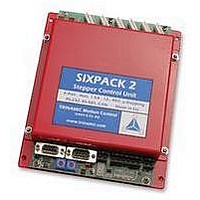
TMC SIXPACK 2
Manufacturer Part Number
TMC SIXPACK 2
Description
CONTROLLER, STEPPER MOTOR, AMPLIF
Manufacturer
TRINAMIC
Datasheet
1.TMC_SIXPACK_2.pdf
(48 pages)
Specifications of TMC SIXPACK 2
Supply Voltage Range
15Vdc To 48Vdc
No. Of Phases
Two
Output Current
1.4A
Approval Bodies
CE
Current Limit Max
1.4A
Current Limit Min
300mA
External Depth
35mm
External Length / Height
180mm
Svhc
No SVHC (15-Dec-2010)
Rohs Compliant
Yes
Lead Free Status / RoHS Status
Lead free / RoHS Compliant


SIXpack 2 – manual (V1.01 / May 5
7.3 Additional Inputs / Outputs
Read Motor Input Channels and additional Inputs
Setting the Limits for the Stop Function left/right
Setting of additional Outputs
Function of the ready Output
The analogue channels are prepared for ratiometric measurements of resistive dividers. Channel 6 is
the external input, channel 7 measures the voltage supply of the PACK (1V equals value 22). The
reference inputs are inverted.
A potentiometer or a resistor network connected to two stop switches at the analogue input of each
motor can trigger a hard or soft stop. The voltage of the analogue input should increase in right
direction (cw). The measured value is checked dependent on the motor direction. When a stop-
condition occurs the motor is stopped immediately. If StopSoft-Flag is set, the motor is in decelerated
with the pre-set acceleration. If the StopSoft Flag isn’t set the motor will be stopped abruptly, so that
the precise motor position may be lost. Therefore a reference search will be started additionally if the
StopNoRef-Flag is not set. When the StopNull-Flag is set, the zero switch also functions as a limit
switch. If the reference switch is defined on the right side, the motor then can only drive in the area of
negative co-ordinates
The ready output can be activated (low, open collector), whenever a motor is active (velocity greater
than 0) or search of reference. The ready output will be switched within 2 ms after start/end motor
movement. The repeatability (jitter) equals approximately the microstep rate during start respectively
stop (s. CMD $13).
CMD
P0
P1
Response
CMD
P0
P1,2 #
P3
P4
P5
CMD
P0
P1,2 #
P3,4 #
CMD
P0
P1
P2
P3
CMD
P0
P1
$30
channel no (0=channel0 ... 7=channel7).
response address
$30
channel no (0...7).
analogue value (unsigned 0..1023)
reference input (Bit 0)
all reference inputs / jumpers (bit 0 = motor 0, ..., bit 6=jumper1, bit 7 = jumper2)
(s. setting the baud rate)
bit 0: logic state at TTLIO1
$31
channel no (0...7):
analogue value minimum for stop left (0=no function)
analogue value maximum for stop right (≥1023=no function)
$32
bit 0: set logic level at TTLOUT1 (1=READY, 0= active)
bit 0: output enable for TTLIO1 (1=input, 0=output)
bit 0: set logic level at TTLIO1
bit 0: 1=TTLOUT1 works as ready output (1=READY, 0= active)
$33
mask for active motors (bit 0=motor 0, bit 5=motor 5)
mask for reference search of a motor (bit 0=motor 0, bit 5=motor 5)
(position <= 0)
th
, 2006) 42
(s. CMD $15)
Related parts for TMC SIXPACK 2
Image
Part Number
Description
Manufacturer
Datasheet
Request
R

Part Number:
Description:
Alarm, Piezoelectric, 75 dBA to 95 dBA @ 2 Ft., Medium Loud Continuous, 30-120VAC
Manufacturer:
Floyd Bell Inc.
Part Number:
Description:
Alarm, Piezoelectric, 75 dBA to 95 dBA @ 2 Ft., Medium Loud Continuous, 9-48VDC
Manufacturer:
Floyd Bell Inc.
Part Number:
Description:
57mm/NEMA23 or 60mm/NEMA24 Stepper Motor with Controller/Driver with Encoder and Serial Interface
Manufacturer:
TRINAMIC [TRINAMIC Motion Control GmbH & Co. KG.]
Datasheet:
Part Number:
Description:
60mm/NEMA24 Stepper Motor with Controller/Driver, with Encoder and Serial Interface
Manufacturer:
TRINAMIC [TRINAMIC Motion Control GmbH & Co. KG.]
Datasheet:
Part Number:
Description:
42mm/NEMA17 Stepper Motor with Controller/Driver, Encoderand Serial Interface
Manufacturer:
TRINAMIC [TRINAMIC Motion Control GmbH & Co. KG.]
Datasheet:

Part Number:
Description:
42mm/NEMA17 High Performance BLDC Motor with Controller/Driver and Serial Interface
Manufacturer:
TRINAMIC [TRINAMIC Motion Control GmbH & Co. KG.]
Datasheet:
Part Number:
Description:
57mm diameter BLDC Encoder Motor with Controller/Driver and Serial Interface
Manufacturer:
TRINAMIC [TRINAMIC Motion Control GmbH & Co. KG.]
Datasheet:
Part Number:
Description:
57mm / NEMA23 Stepper Motor with Controller / Driver and Serial Interface
Manufacturer:
TRINAMIC [TRINAMIC Motion Control GmbH & Co. KG.]
Datasheet:
Part Number:
Description:
42mm / NEMA17 Stepper Motor with Controller / Driver and Serial Interface
Manufacturer:
TRINAMIC [TRINAMIC Motion Control GmbH & Co. KG.]
Datasheet:
