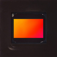
MT9V022IA7ATM Aptina LLC, MT9V022IA7ATM Datasheet - Page 25

MT9V022IA7ATM
Manufacturer Part Number
MT9V022IA7ATM
Description
SENSOR IMAGE VGA MONO 52IBGA
Manufacturer
Aptina LLC
Type
CMOS Imagingr
Series
DigitalClarity®r
Specifications of MT9V022IA7ATM
Pixel Size
6µm x 6µm
Active Pixel Array
752H x 480V
Frames Per Second
60
Voltage - Supply
3.3V
Package / Case
52-IBGA
Sensor Image Color Type
Monochrome
Sensor Image Size Range
250,920 to 480,000Pixels
Sensor Image Size
752x480Pixels
Operating Supply Voltage (min)
3V
Operating Supply Voltage (typ)
3.3V
Operating Supply Voltage (max)
3.6V
Operating Temp Range
-40C to 85C
Package Type
IBGA
Operating Temperature Classification
Industrial
Mounting
Surface Mount
Pin Count
52
Lead Free Status / RoHS Status
Lead free / RoHS Compliant
Other names
557-1205
Available stocks
Company
Part Number
Manufacturer
Quantity
Price
Changes to Integration Time
Figure 20:
PDF: 3295348826/Source:7478516499
MT9V022_DS - Rev.H 6/10 EN
Latency When Changing Integration
1. During frame n, the new integration time is held in the R0x0B live register.
2. At the start of frame (n + 1), the new integration time is transferred to the exposure
3. When frame (n + 1) is read out, it is integrated using the new integration time. If the
With automatic exposure control disabled (R0xAF, bit 0 is cleared to LOW), and if the
total integration time (R0x0B) is changed via the two-wire serial interface while
FRAME_VALID is asserted for frame n, the first frame output using the new integration
time is frame (n + 2). Similarly, when automatic exposure control is enabled, any change
to the integration time for frame n first appears in frame (n + 2) output.
The sequence is as follows:
New Integration
FRAME_VALID
Programmed
control module. Integration for each row of frame (n + 1) has been completed using
the old integration time. The earliest time that a row can start integrating using the
new integration time is immediately after that row has been read for frame (n + 1).
The actual time that rows start integrating using the new integration time is depen-
dent on the new value of the integration time.
integration time is changed (R0x0B written) on successive frames, each value written
is applied to a single frame; the latency between writing a value and it affecting the
frame readout remains at two frames.
However, when automatic exposure control is disabled, if the integration time is
changed through the two-wire serial interface after the falling edge of FRAME_VALID
for frame n, the first frame output using the new integration time becomes frame
(n + 3).
Image Data
Integration
LED_OUT
Actual
Frame Start
Int = 200 rows
25
Int = 200 rows
MT9V022: 1/3-Inch Wide-VGA Digital Image Sensor
Output image with
Int = 200 rows
Int = 300 rows
Aptina reserves the right to change products or specifications without notice.
Int = 300 rows
©2005 Aptina Imaging Corporation. All rights reserved.
Output
image with
Int = 300
rows
Feature Description


