CYIL2SM1300AA-GZDC Cypress Semiconductor Corp, CYIL2SM1300AA-GZDC Datasheet - Page 16
CYIL2SM1300AA-GZDC
Manufacturer Part Number
CYIL2SM1300AA-GZDC
Description
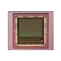
IMAGE SENSOR CMOS LUPA-1300-3
Manufacturer
Cypress Semiconductor Corp
Type
CMOS Imagingr
Specifications of CYIL2SM1300AA-GZDC
Package / Case
168-PGA
Pixel Size
14µm x 14µm
Active Pixel Array
1280H x 1024V
Frames Per Second
500
Voltage - Supply
2.5V, 3.3V
Operating Supply Voltage
2.5 V
Maximum Power Dissipation
1350 mW
Maximum Operating Temperature
+ 70 C
Supply Current
80 mA
Minimum Operating Temperature
0 C
Package
168CuPGA
Image Size
1280x1024 Pixels
Color Sensing
Monochrome
Operating Temperature
0 to 70 °C
Lead Free Status / RoHS Status
Lead free / RoHS Compliant
Lead Free Status / RoHS Status
Lead free / RoHS Compliant, Lead free / RoHS Compliant


Datachannels. DatachannelX_1 and DatachannelX_2 (with
X=0 to 12) are registers that allow you to enable or disable the
FPN correction (DatachannelX_1[1]), and generate a test
pattern
datachannelX_2[7:0]).
Sequencer Block
The sequencer block group registers allow enabling or disabling
image sensor features that are driven by the onboard sequencer.
This block consists of the following registers:
Seqmode1. The seqmode1 registers have the following
subregisters:
Seqmode1[0]: Enables image capture, must be '1' during image
acquisition.
Seqmode1[1]: This subregister has two modes:
'1': In this default mode the integration timing is generated
on-chip.
'0': In this slave mode, the integration timing must be generated
through the int_time1, int_time2, and int_time3 pins.
Seqmode1[2]: This bit enables pipelined (0) or triggered (1)
mode.
Seqmode1[3]: Enable (1) or disable (0) subsampling.
Seqmode1[4]: This bit sets the type of subsampling scheme
used when subsampling is enabled.
'1': Color (1:1:0:0:1:1:0:0:1…)
'0': Black and White (1:0:1:0:1)
Seqmode1[5]: This bit enables or disables the dual slope
integration.
Seqmode1[6]: This bit enables or disables the triple slope
integration.
Seqmode2. The seqmode2 register consists of only two
subregisters:
Seqmode2[4:0]: Default value after startup is '10000', but this
must be overwritten with the new value '10001' immediately after
startup.
Seqmode3[6:5]: These two bits set the number of active
windows:
'00': 1 window
'01': 2 windows
'10': 3 windows
'11': 4 windows (max)
Seqmode3. The seqmode3 register consists of the following
subregisters:
Seqmode3[0]: This bit enables or disables the CRC10
generation on the data and sync channels
Seqmode3[1]: Enables or disables black level calibration
Seqmode3[2]: Enables or disables column FPN correction
Seqmode3[5:3]: Enables or disables, and sets the number of
frames grabbed in nondestructive readout mode.
'000': Invalid
'001': Default, 1 reset, 1 sample
'010': 1reset, 2 samples
'011': 1 reset, 3 samples
Document Number: 001-24599 Rev. *C
if
necessary
(datachannelX_1[5:4]
and
Seqmode3[6]: Controls the granularity of the timer settings (only
for those that have 'granularity selectable' in the description). As
a result, all timer settings are set either in number of applied clock
cycles, or in the number of 'readout lines'.
'0': expressed in number of lines
'1': expressed in clock cycles (multiplied by 2**seqmode4 [3:0])
Seqmode3[7]: Allows syncing of events that happen outside of
ROT to be delayed to the next ROT to avoid image artifacts.
Seqmode4. This register consists of four subregisters:
Seqmode4[3:0]: Multiplier factor (2**seqmode4[3:0]) for the
timers when working in clock cycle mode.
Seqmode4[5:4]: Selects the source signals to be put on the
digital test pins (monitor1, monitor2, and monitor3 pins)
"00": integration time settings
"01": EOS signals
"10": frame sync signals
"11": functional test mode
Seqmode4[6]: Enables (1) and disables (0) reverse X read out.
Seqmode4[7]: Enables (1) and disables (0) reverse Y read out.
Y1_start (60 and 61, 10 bit). These registers set the Y start
address for window 1 (default window).
X1_start (61, 6bit). This register sets the X start address for
window 1 (default window).
Y1_end (62 and 63, 10 bit). These registers set the Y end
address for window 1 (default window).
X1_kernels (63, 6 bit). This register sets the number of kernels
or X width to be read out for window 1 (default window).
Y2_start (64 and 65, 10 bit). These registers set the Y start
address for window 2 (if enabled).
X2_start (65, 6bit). This register sets the X start address for
window 2 (if enabled).
Y2_end (66 and 67, 10 bit). These registers set the Y end
address for window 2 (if enabled).
X2_kernels (67, 6 bit). This register sets the number of kernels
or X width to be read out for window 2 (if enabled).
Y3_start (68 and 69, 10 bit). These registers set the Y start
address for window 3 (if enabled).
X3_start (69, 6bit). This register sets the X start address for
window 3 (if enabled).
Y3_end (70 and 71, 10 bit). These registers set the Y end
address for window 3 (if enabled).
X3_kernels (71, 6 bit). This register sets the number of kernels
or X width to be read out for window 3 (if enabled).
Y4_start (72 and 73, 10 bit). These registers set the Y start
address for window 4 (if enabled).
X4_start (73, 6bit). This register sets the X start address for
window 4 (if enabled).
Y4_end (74 and 75, 10 bit). These registers set the Y end
address for window 4 (if enabled).
X4_kernels (75, 6 bit). This register sets the number of kernels
or X width to be read out for window 4 (if enabled).
CYIL2SM1300AA
Page 16 of 41
[+] Feedback
Related parts for CYIL2SM1300AA-GZDC
Image
Part Number
Description
Manufacturer
Datasheet
Request
R

Part Number:
Description:
BOARD EVAL IMG SENS LUPA-1300-2
Manufacturer:
Cypress Semiconductor Corp
Datasheet:
Part Number:
Description:
Manufacturer:
Cypress Semiconductor Corp
Datasheet:
Part Number:
Description:
Manufacturer:
Cypress Semiconductor Corp
Datasheet:
Part Number:
Description:
Manufacturer:
Cypress Semiconductor Corp
Datasheet:
Part Number:
Description:
Manufacturer:
Cypress Semiconductor Corp
Datasheet:
Part Number:
Description:
Manufacturer:
Cypress Semiconductor Corp
Datasheet: