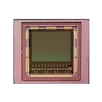
CYIL2SM1300AA-GZDC Cypress Semiconductor Corp, CYIL2SM1300AA-GZDC Datasheet - Page 23

CYIL2SM1300AA-GZDC
Manufacturer Part Number
CYIL2SM1300AA-GZDC
Description
IMAGE SENSOR CMOS LUPA-1300-3
Manufacturer
Cypress Semiconductor Corp
Type
CMOS Imagingr
Specifications of CYIL2SM1300AA-GZDC
Package / Case
168-PGA
Pixel Size
14µm x 14µm
Active Pixel Array
1280H x 1024V
Frames Per Second
500
Voltage - Supply
2.5V, 3.3V
Operating Supply Voltage
2.5 V
Maximum Power Dissipation
1350 mW
Maximum Operating Temperature
+ 70 C
Supply Current
80 mA
Minimum Operating Temperature
0 C
Package
168CuPGA
Image Size
1280x1024 Pixels
Color Sensing
Monochrome
Operating Temperature
0 to 70 °C
Lead Free Status / RoHS Status
Lead free / RoHS Compliant
Lead Free Status / RoHS Status
Lead free / RoHS Compliant, Lead free / RoHS Compliant
Figure 19
single window mode (except that in this case, the maximum integration time is equal to the sum of the y_widths of the two windows).
Read out starts with a FOT that is similar to single window mode. After the FOT, all lines of window 1 are read, followed by the lines
of window 2.
If the X size of the windows are not identical, the integration time
in function of the number of lines read presents multiple slopes
(proportional to the X size of these windows). Because this can
cause confusion when programming the integration time, it is
easier to configure all timer registers using the clock cycle
configuration instead of the 'line' configuration.
Multiple Slopes
Dynamic range can be extended by the multiple slope
capabilities of the sensor. The four colored lines in
represent analog signals of the photodiode of four pixels, which
decrease as a result of exposure. The slope is determined by the
amount of light at each pixel (the more light, the steeper the
slope). When the pixels reach the saturation level, the analog
does not change despite further exposure. Without the multiple
Document Number: 001-24599 Rev. *C
shows the sequence of integration and read out for multiple windows. The handling of integration time is identical to the
Int. Time
Handling
Readout
Handling
Figure 20. Dynamic Range Extended by Multiple Slope Capability
FOT
Figure 19. Exposure and Read Out of Multiple Windows
ROT
Line Readout Window 1
Line Readout Window 2
Reset N
Readout N-1
Window 1
Exposure Time N
Figure 20
Readout
Window
N-1
2
slope capabilities, the pixels p3 and p4 are saturated before the
end of the exposure time, and no signal is received. However,
when using multiple slopes, the analog signal is reset to a
second or third reset level (lower than the original) before the
integration time ends. The analog signal starts decreasing with
the same slope as before, and pixels that were saturated before
could be nonsaturated at read out time. For pixels that never
reach any of the reset levels (for example, p1 and p2) there is no
difference between single and multiple slope operation.
By choosing the time stamps of the double and triple slope resets
(typical at 90% and 99% of the integration, configurable by the
user), it is possible to have a nonsaturated pixel value even for
pixels that receive a huge amount of light.
FOT
Reset
N+1
Readout N
Window 2
Exposure Time
Readout N
t
CYIL2SM1300AA
Page 23 of 41
[+] Feedback


