CYIL2SM1300AA-GZDC Cypress Semiconductor Corp, CYIL2SM1300AA-GZDC Datasheet - Page 21
CYIL2SM1300AA-GZDC
Manufacturer Part Number
CYIL2SM1300AA-GZDC
Description
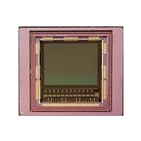
IMAGE SENSOR CMOS LUPA-1300-3
Manufacturer
Cypress Semiconductor Corp
Type
CMOS Imagingr
Specifications of CYIL2SM1300AA-GZDC
Package / Case
168-PGA
Pixel Size
14µm x 14µm
Active Pixel Array
1280H x 1024V
Frames Per Second
500
Voltage - Supply
2.5V, 3.3V
Operating Supply Voltage
2.5 V
Maximum Power Dissipation
1350 mW
Maximum Operating Temperature
+ 70 C
Supply Current
80 mA
Minimum Operating Temperature
0 C
Package
168CuPGA
Image Size
1280x1024 Pixels
Color Sensing
Monochrome
Operating Temperature
0 to 70 °C
Lead Free Status / RoHS Status
Lead free / RoHS Compliant
Lead Free Status / RoHS Status
Lead free / RoHS Compliant, Lead free / RoHS Compliant


Master Mode
In this mode, a rising edge on int_time1 pin is used to trigger the
start of integration and read out. The tint_timer defines the
integration time independent of the assertion of the input pin
int_time1. After the integration time counter runs out, the FOT
automatically starts and the image readout is done. During
readout, the image array is kept in reset. A request for a new
frame is started again when a new rising edge on int_time is
detected. The time of the falling edge is not important in this
mode.
Windowing
A fully configurable window can be selected for readout.
The parameters to configure this window are:
x_start. The sensor reads out 24 pixels in one single clock cycle.
The granularity of configuring the X start position is also 24.
Every value written to the windowX_2 register must be multiplied
by 24 to find the corresponding column in the pixel array.
x_kernels. The number of columns that is read out
(x_kernels*24 in full frame mode) in subsampling mode
x_kernels*48 represents the number of columns over which
subsampling is done. The x_kernels value must be written to the
windowX_4 register.
y_start. The starting line of the readout window, granularity of 1.
Note that in subsample mode, the correct y_start position must
be uploaded (exact value depends on color or B/W subsampling
mode). This value must be written to the windowX_1 and
windowx_2 register.
Document Number: 001-24599 Rev. *C
y start
y_end
x start
Figure 16. Window Selected for Readout
x kernel
1280 pixels
Slave Mode
Integration time control is identical to the pipelined shutter slave
mode. The int_time1 pin controls the start of integration. When
int_time is deasserted, the FOT starts (analog value on the pixel
diode is transferred to the pixel memory element). Only at that
time, image read out can start (similar to the pipelined read out).
During read out, the image array is kept in reset. A request for a
new frame is started when int_time goes high again.
y_end. The end line of the readout window, granularity of 1. In
all cases (even in reverse scan), y_end are larger than y_start.
Note that in subsample mode, the correct y_end position must
be uploaded (exact value depends on color or B/W subsampling
mode). This value must be written to the windowX_3 and
windowX_4 register.
In case of windowing, the effective readout time is smaller than
in full frame mode, because only the relevant part of the image
array is accessed. As a result, it is possible to achieve higher
frame rates.
1024 pixels
CYIL2SM1300AA
Page 21 of 41
[+] Feedback
Related parts for CYIL2SM1300AA-GZDC
Image
Part Number
Description
Manufacturer
Datasheet
Request
R

Part Number:
Description:
BOARD EVAL IMG SENS LUPA-1300-2
Manufacturer:
Cypress Semiconductor Corp
Datasheet:
Part Number:
Description:
Manufacturer:
Cypress Semiconductor Corp
Datasheet:
Part Number:
Description:
Manufacturer:
Cypress Semiconductor Corp
Datasheet:
Part Number:
Description:
Manufacturer:
Cypress Semiconductor Corp
Datasheet:
Part Number:
Description:
Manufacturer:
Cypress Semiconductor Corp
Datasheet:
Part Number:
Description:
Manufacturer:
Cypress Semiconductor Corp
Datasheet: