CYIL2SM1300AA-GZDC Cypress Semiconductor Corp, CYIL2SM1300AA-GZDC Datasheet - Page 20
CYIL2SM1300AA-GZDC
Manufacturer Part Number
CYIL2SM1300AA-GZDC
Description
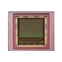
IMAGE SENSOR CMOS LUPA-1300-3
Manufacturer
Cypress Semiconductor Corp
Type
CMOS Imagingr
Specifications of CYIL2SM1300AA-GZDC
Package / Case
168-PGA
Pixel Size
14µm x 14µm
Active Pixel Array
1280H x 1024V
Frames Per Second
500
Voltage - Supply
2.5V, 3.3V
Operating Supply Voltage
2.5 V
Maximum Power Dissipation
1350 mW
Maximum Operating Temperature
+ 70 C
Supply Current
80 mA
Minimum Operating Temperature
0 C
Package
168CuPGA
Image Size
1280x1024 Pixels
Color Sensing
Monochrome
Operating Temperature
0 to 70 °C
Lead Free Status / RoHS Status
Lead free / RoHS Compliant
Lead Free Status / RoHS Status
Lead free / RoHS Compliant, Lead free / RoHS Compliant


Slave Mode
In slave mode, the register values of res_length and tint_timer are ignored. The integration time is controlled by the int_time pin. The
relationship between the input pin and the integration time is shown in
array goes out of reset and exposure can begin. When int_time goes low again and the desired exposure time is reached, the image
is sampled and read out can begin.
Changing a pixel's reset level during line readout might result in image artefacts during a small transient period. As a result, it is advised
to only change the value of int_time during ROT.
Triggered Shutter
The two main differences in the pipelined shutter mode are:
■
■
This means that for every frame, you need to manually intervene. The pixel array is kept in reset state until you assert the int_time
input. Similar to the pipelined shutter mode, there is a master mode in which the sequencer can control the integration time, or a slave
mode in which you can define the integration time.
The possible applications for this triggered shutter mode are:
■
■
Document Number: 001-24599 Rev. *C
One single image is read upon every user action.
Integration (and read out) is under control of the user through pin int_time.
Synchronize external flash with exposure
Apply extremely long integration times (only in slave mode)
Handling
int_time1
Int. Time
Readout
Handling
Figure 14. Integration and Image Readout in Slave Mode
Figure 15. Integration and Readout for Triggered Shutter
Reset Exposure Time N
ROT
Line
Readout
FOT
Readout N
Reset
Figure
14. When the input pin int_time is asserted, the pixel
Exposure Time N
FOT
out
Reset
Read
CYIL2SM1300AA
N+1
N+1
Page 20 of 41
[+] Feedback
Related parts for CYIL2SM1300AA-GZDC
Image
Part Number
Description
Manufacturer
Datasheet
Request
R

Part Number:
Description:
BOARD EVAL IMG SENS LUPA-1300-2
Manufacturer:
Cypress Semiconductor Corp
Datasheet:
Part Number:
Description:
Manufacturer:
Cypress Semiconductor Corp
Datasheet:
Part Number:
Description:
Manufacturer:
Cypress Semiconductor Corp
Datasheet:
Part Number:
Description:
Manufacturer:
Cypress Semiconductor Corp
Datasheet:
Part Number:
Description:
Manufacturer:
Cypress Semiconductor Corp
Datasheet:
Part Number:
Description:
Manufacturer:
Cypress Semiconductor Corp
Datasheet: