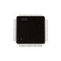
SAA7324H NXP Semiconductors, SAA7324H Datasheet - Page 13

SAA7324H
Manufacturer Part Number
SAA7324H
Description
Manufacturer
NXP Semiconductors
Datasheet
1.SAA7324H.pdf
(68 pages)
Specifications of SAA7324H
Operating Temperature (max)
70C
Operating Temperature Classification
Commercial
Mounting
Surface Mount
Pin Count
64
Lead Free Status / Rohs Status
Compliant
Available stocks
Company
Part Number
Manufacturer
Quantity
Price
Company:
Part Number:
SAA7324H
Manufacturer:
PHILIPS
Quantity:
84
Company:
Part Number:
SAA7324H/M2B,557
Manufacturer:
NXP Semiconductors
Quantity:
10 000
Company:
Part Number:
SAA7324H/T/M2B
Manufacturer:
NXP
Quantity:
5 000
Part Number:
SAA7324H/T/M2B
Manufacturer:
PHILIPS/飞利浦
Quantity:
20 000
Philips Semiconductors
7.5
7.5.1
The 96-bit Q-channel word is accumulated in an internal
buffer. The last 16 bits are used internally to perform a
Cyclic Redundancy Check (CRC). If the data is good, the
SUBQREADY-I signal will go LOW. SUBQREADY-I can
be read via the SDA or STATUS pins, selected via decoder
register 2. Good Q-channel data may be read from SDA.
7.5.2
Data from all the subcode channels (P-to-W) may be read
via the subcode interface, which conforms to
EIAJ CP-2401. The interface is enabled and configured as
either a 3 or 4-wire interface via decoder register F.
2000 Jun 26
handbook, full pagewidth
Digital servo processor and Compact Disc
decoder with integrated DAC (CD10 II)
Subcode data processing
Q-
EIAJ 3
INTERFACES
SBSY
SFSY
RCK
SUB
SFSY
RCK
SUB
CHANNEL PROCESSING
AND
4-
WIRE SUBCODE
SF0
SF0
Fig.8 EIAJ subcode (CD graphics) interface format.
SFSY
RCK
SUB
SF1
SF1
(CD
GRAPHICS
P
P-W
EIAJ 4-wire subcode interface
P-W
EIAJ 3-wire subcode interface
SF2
SF2
Q
)
R
S
13
P-W
P-W
SF3
SF3
The subcode interface output formats are illustrated in
Fig.8, where the RCK signal is supplied by another device
such as a CD graphics decoder.
7.5.3
Data of subcode channels, Q-to-W, may be read via pin V4
if selected via decoder register D. The format is similar to
RS232 and is illustrated in Fig.9. The subcode sync word
is formed by a pause of (200/n) s minimum. Each
subcode byte starts with a logic 1 followed by 7 bits
(Q-to-W). The gap between bytes is variable between
(11.3/n) s and (90/n) s.
The subcode data is also available in the EBU output
(DOBM) in a similar format.
T
U
V
V4
W
SUBCODE INTERFACE
SF97
SF97
P-W
P-W
SF0
SF0
Product specification
SF1
SF1
SAA7324
MBG410


