EP1SGX25DF672I6 Altera, EP1SGX25DF672I6 Datasheet - Page 131
EP1SGX25DF672I6
Manufacturer Part Number
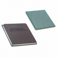
EP1SGX25DF672I6
Description
IC STRATIX GX FPGA 25K 672-FBGA
Manufacturer
Altera
Series
Stratix® GXr
Datasheet
1.EP1SGX10CF672C7N.pdf
(272 pages)
Specifications of EP1SGX25DF672I6
Number Of Logic Elements/cells
25660
Number Of Labs/clbs
2566
Total Ram Bits
1944576
Number Of I /o
455
Voltage - Supply
1.425 V ~ 1.575 V
Mounting Type
Surface Mount
Operating Temperature
-40°C ~ 100°C
Package / Case
672-FBGA
Family Name
Stratix GX
Number Of Logic Blocks/elements
25660
# I/os (max)
455
Frequency (max)
5GHz
Process Technology
SRAM
Operating Supply Voltage (typ)
1.5V
Logic Cells
25660
Ram Bits
1944576
Operating Supply Voltage (min)
1.425V
Operating Supply Voltage (max)
1.575V
Operating Temp Range
-40C to 100C
Operating Temperature Classification
Industrial
Mounting
Surface Mount
Pin Count
672
Package Type
FC-FBGA
Lead Free Status / RoHS Status
Contains lead / RoHS non-compliant
Number Of Gates
-
Lead Free Status / Rohs Status
Not Compliant
Available stocks
Company
Part Number
Manufacturer
Quantity
Price
Company:

Part Number:
EP1SGX25DF672I6
Manufacturer:
ALTERA30
Quantity:
50


Altera Corporation
February 2005
Note to
(1)
Multiplier
Multiply-accumulator
Two-multipliers adder
Four-multipliers adder
Table 4–15. Multiplier Size & Configurations per DSP block
The number of supported multiply functions shown is based on signed/signed or unsigned/unsigned
implementations.
DSP Block Mode
Table
4–15:
For FIR filters, the DSP block combines the four-multipliers adder mode
with the shift register inputs. One set of shift inputs contains the filter
data, while the other holds the coefficients loaded in serial or parallel. The
input shift register eliminates the need for shift registers external to the
DSP block (that is, implemented in LEs). This architecture simplifies filter
design since the DSP block implements all of the filter circuitry.
One DSP block can implement an entire 18-bit FIR filter with up to four
taps. For FIR filters larger than four taps, DSP blocks can be cascaded with
additional adder stages implemented in LEs.
Table 4–15
DSP block mode according to size. These modes allow the DSP blocks to
implement numerous applications for DSP including FFTs, complex FIR,
FIR, and 2D FIR filters, equalizers, IIR, correlators, matrix multiplication
and many other functions.
DSP Block Interface
Stratix GX device DSP block outputs can cascade down within the same
DSP block column. Dedicated connections between DSP blocks provide
fast connections between the shift register inputs to cascade the shift
register chains. You can cascade DSP blocks for 9
filters larger than four taps, with additional adder stages implemented in
LEs. If the DSP block is configured as 36
accumulator stages are implemented in LEs. Each DSP block can route the
shift register chain out of the block to cascade two full columns of DSP
blocks.
Eight multipliers with
eight product outputs
Two multiply and
accumulate (52 bits)
Four sums of two
multiplier products each
Two sums of four
multiplier products each
9
shows the different number of multipliers possible in each
×
9
Four multipliers with four
product outputs
Two multiply and
accumulate (52 bits)
Two sums of two
multiplier products each
One sum of four multiplier
products each
18
Stratix GX Device Handbook, Volume 1
×
18
×
36 bits, the adder, subtractor, or
One multiplier with one
product output
×
–
–
–
Stratix GX Architecture
9- or 18
36
×
×
36
18-bit FIR
(1)
4–65
Related parts for EP1SGX25DF672I6
Image
Part Number
Description
Manufacturer
Datasheet
Request
R

Part Number:
Description:
Stratix Gx Device Family Data Sheet
Manufacturer:
Altera Corporation
Datasheet:

Part Number:
Description:
CYCLONE II STARTER KIT EP2C20N
Manufacturer:
Altera
Datasheet:

Part Number:
Description:
CPLD, EP610 Family, ECMOS Process, 300 Gates, 16 Macro Cells, 16 Reg., 16 User I/Os, 5V Supply, 35 Speed Grade, 24DIP
Manufacturer:
Altera Corporation
Datasheet:
Part Number:
Description:
CPLD, EP610 Family, ECMOS Process, 300 Gates, 16 Macro Cells, 16 Reg., 16 User I/Os, 5V Supply, 15 Speed Grade, 24DIP
Manufacturer:
Altera Corporation
Datasheet:
Part Number:
Description:
Manufacturer:
Altera Corporation
Datasheet:
Part Number:
Description:
CPLD, EP610 Family, ECMOS Process, 300 Gates, 16 Macro Cells, 16 Reg., 16 User I/Os, 5V Supply, 30 Speed Grade, 24DIP
Manufacturer:
Altera Corporation
Datasheet:
Part Number:
Description:
High-performance, low-power erasable programmable logic devices with 8 macrocells, 10ns
Manufacturer:
Altera Corporation
Datasheet:
Part Number:
Description:
High-performance, low-power erasable programmable logic devices with 8 macrocells, 7ns
Manufacturer:
Altera Corporation
Datasheet:
Part Number:
Description:
Classic EPLD
Manufacturer:
Altera Corporation
Datasheet:
Part Number:
Description:
High-performance, low-power erasable programmable logic devices with 8 macrocells, 10ns
Manufacturer:
Altera Corporation
Datasheet:
Part Number:
Description:
Manufacturer:
Altera Corporation
Datasheet:
Part Number:
Description:
Manufacturer:
Altera Corporation
Datasheet:
Part Number:
Description:
Manufacturer:
Altera Corporation
Datasheet: