EP1SGX25DF672I6 Altera, EP1SGX25DF672I6 Datasheet - Page 194
EP1SGX25DF672I6
Manufacturer Part Number
EP1SGX25DF672I6
Description
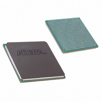
IC STRATIX GX FPGA 25K 672-FBGA
Manufacturer
Altera
Series
Stratix® GXr
Datasheet
1.EP1SGX10CF672C7N.pdf
(272 pages)
Specifications of EP1SGX25DF672I6
Number Of Logic Elements/cells
25660
Number Of Labs/clbs
2566
Total Ram Bits
1944576
Number Of I /o
455
Voltage - Supply
1.425 V ~ 1.575 V
Mounting Type
Surface Mount
Operating Temperature
-40°C ~ 100°C
Package / Case
672-FBGA
Family Name
Stratix GX
Number Of Logic Blocks/elements
25660
# I/os (max)
455
Frequency (max)
5GHz
Process Technology
SRAM
Operating Supply Voltage (typ)
1.5V
Logic Cells
25660
Ram Bits
1944576
Operating Supply Voltage (min)
1.425V
Operating Supply Voltage (max)
1.575V
Operating Temp Range
-40C to 100C
Operating Temperature Classification
Industrial
Mounting
Surface Mount
Pin Count
672
Package Type
FC-FBGA
Lead Free Status / RoHS Status
Contains lead / RoHS non-compliant
Number Of Gates
-
Lead Free Status / Rohs Status
Not Compliant
Available stocks
Company
Part Number
Manufacturer
Quantity
Price
Company:

Part Number:
EP1SGX25DF672I6
Manufacturer:
ALTERA30
Quantity:
50


Configuration
5–2
Stratix GX Device Handbook, Volume 1
and before and during configuration. Together, the configuration and
initialization processes are called command mode. Normal device
operation is called user mode.
A built-in weak pull-up resistor pulls all user I/O pins to V
and during device configuration.
SRAM configuration elements allow Stratix GX devices to be
reconfigured in-circuit by loading new configuration data into the device.
With real-time reconfiguration, the device is forced into command mode
with a device pin. The configuration process loads different configuration
data, reinitializes the device, and resumes user-mode operation. You can
perform in-field upgrades by distributing new configuration files either
within the system or remotely.
Configuration Schemes
You can load the configuration data for a Stratix GX device with one of
five configuration schemes (see
target application. You can use a configuration device, intelligent
controller, or the JTAG port to configure a Stratix GX device. A
configuration device can automatically configure a Stratix GX device at
system power-up.
You can configure multiple Stratix GX devices in any of five
configuration schemes by connecting the configuration enable (nCE) and
configuration enable output (nCEO) pins on each device.
Configuration device
Passive serial (PS)
Passive parallel
asynchronous (PPA)
Fast passive parallel
JTAG
Table 5–1. Data Sources for Configuration
Configuration Scheme
Enhanced or EPC2 configuration device
ByteBlasterMV™ or MasterBlaster™ download
cable or serial data source
Parallel data source
Parallel data source
MasterBlaster or ByteBlasterMV download cable
or a microprocessor with a Jam or JBC file (.jam
or .jbc)
Table
5–1), chosen on the basis of the
Data Source
Altera Corporation
February 2005
CCIO
before
Related parts for EP1SGX25DF672I6
Image
Part Number
Description
Manufacturer
Datasheet
Request
R

Part Number:
Description:
Stratix Gx Device Family Data Sheet
Manufacturer:
Altera Corporation
Datasheet:

Part Number:
Description:
CYCLONE II STARTER KIT EP2C20N
Manufacturer:
Altera
Datasheet:

Part Number:
Description:
CPLD, EP610 Family, ECMOS Process, 300 Gates, 16 Macro Cells, 16 Reg., 16 User I/Os, 5V Supply, 35 Speed Grade, 24DIP
Manufacturer:
Altera Corporation
Datasheet:
Part Number:
Description:
CPLD, EP610 Family, ECMOS Process, 300 Gates, 16 Macro Cells, 16 Reg., 16 User I/Os, 5V Supply, 15 Speed Grade, 24DIP
Manufacturer:
Altera Corporation
Datasheet:
Part Number:
Description:
Manufacturer:
Altera Corporation
Datasheet:
Part Number:
Description:
CPLD, EP610 Family, ECMOS Process, 300 Gates, 16 Macro Cells, 16 Reg., 16 User I/Os, 5V Supply, 30 Speed Grade, 24DIP
Manufacturer:
Altera Corporation
Datasheet:
Part Number:
Description:
High-performance, low-power erasable programmable logic devices with 8 macrocells, 10ns
Manufacturer:
Altera Corporation
Datasheet:
Part Number:
Description:
High-performance, low-power erasable programmable logic devices with 8 macrocells, 7ns
Manufacturer:
Altera Corporation
Datasheet:
Part Number:
Description:
Classic EPLD
Manufacturer:
Altera Corporation
Datasheet:
Part Number:
Description:
High-performance, low-power erasable programmable logic devices with 8 macrocells, 10ns
Manufacturer:
Altera Corporation
Datasheet:
Part Number:
Description:
Manufacturer:
Altera Corporation
Datasheet:
Part Number:
Description:
Manufacturer:
Altera Corporation
Datasheet:
Part Number:
Description:
Manufacturer:
Altera Corporation
Datasheet: