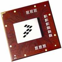
MPC8560CPX667JC Freescale Semiconductor, MPC8560CPX667JC Datasheet - Page 94

MPC8560CPX667JC
Manufacturer Part Number
MPC8560CPX667JC
Description
IC MPU PWRQUICC III 783-FCPBGA
Manufacturer
Freescale Semiconductor
Series
PowerQUICC IIIr
Specifications of MPC8560CPX667JC
Processor Type
MPC85xx PowerQUICC III 32-Bit
Speed
667MHz
Voltage
1.2V
Mounting Type
Surface Mount
Package / Case
783-FCPBGA
Core Size
32 Bit
Program Memory Size
64KB
Cpu Speed
667MHz
Embedded Interface Type
I2C, MII, SPI, TDM, UTOPIA
Digital Ic Case Style
BGA
No. Of Pins
783
Rohs Compliant
No
Family Name
MPC85XX
Device Core
PowerQUICC III
Device Core Size
32b
Frequency (max)
667MHz
Instruction Set Architecture
RISC
Supply Voltage 1 (typ)
1.2V
Operating Supply Voltage (max)
1.26V
Operating Supply Voltage (min)
1.14V
Operating Temp Range
-40C to 105C
Operating Temperature Classification
Industrial
Mounting
Surface Mount
Pin Count
783
Package Type
FCBGA
For Use With
MPC8560ADS-BGA - BOARD APPLICATION DEV 8560
Lead Free Status / RoHS Status
Contains lead / RoHS non-compliant
Features
-
Lead Free Status / Rohs Status
Not Compliant
Available stocks
Company
Part Number
Manufacturer
Quantity
Price
Company:
Part Number:
MPC8560CPX667JC
Manufacturer:
Freescale Semiconductor
Quantity:
10 000
System Design Information
When data is held high, SW1 is closed (SW2 is open) and R
OV
other in value. Then, Z
The output impedance of the RapidIO port drivers targets 200-Ω differential resistance. The value of this
resistance and the strength of the driver’s current source can be found by making two measurements. First,
the output voltage is measured while driving logic 1 without an external differential termination resistor.
The measured voltage is V
1 with an external precision differential termination resistor of value R
V
drive current is then I
Table 61
nominal OV
94
Note: Nominal supply voltages. See
Impedance
2
Differential
= 1/(1/R
DD
R
R
/2. R
N
P
summarizes the signal impedance targets. The driver impedance are targeted at minimum V
P
1
DD
then becomes the resistance of the pull-up devices. R
+ 1/R
, 105°C.
Local Bus, Ethernet, DUART, Control,
Configuration, Power Management
2
)) × I
source
0
MPC8560 Integrated Processor Hardware Specifications, Rev. 4.2
= (R
source
1
= V
= R
P
43 Target
43 Target
. Solving for the output impedance gives R
+ R
Table
1
source
Figure 59. Driver Impedance Measurement
/R
NA
Data
N
source
Table 61. Impedance Characteristics
)/2.
1, T
× I
j
.
source
= 105°C.
. Second, the output voltage is measured while driving logic
PCI/PCI-X
25 Target
25 Target
Pad
P
NA
R
R
is trimmed until the voltage at the pad equals
OV
OGND
N
P
DD
P
and R
SW2
SW1
DDR DRAM
20 Target
20 Target
term
NA
N
source
are designed to be close to each
. The measured voltage is
= R
200 Target
RapidIO
term
NA
NA
Freescale Semiconductor
× (V
Symbol
1
Z
/V
Z
Z
DIFF
0
0
2
– 1). The
Unit
W
W
W
DD
,


