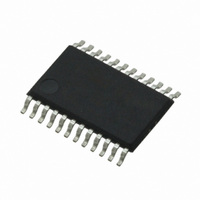
CS4270-DZZ Cirrus Logic Inc, CS4270-DZZ Datasheet - Page 24

CS4270-DZZ
Manufacturer Part Number
CS4270-DZZ
Description
IC CODEC 24BIT 105DB 24TSSOP
Manufacturer
Cirrus Logic Inc
Type
Stereo Audior
Specifications of CS4270-DZZ
Data Interface
Serial
Resolution (bits)
24 b
Number Of Adcs / Dacs
2 / 2
Sigma Delta
Yes
Dynamic Range, Adcs / Dacs (db) Typ
105 / 105
Voltage - Supply, Analog
3.1 V ~ 5.25 V
Voltage - Supply, Digital
3.1 V ~ 5.25 V
Operating Temperature
-40°C ~ 85°C
Mounting Type
Surface Mount
Package / Case
24-TSSOP
Audio Codec Type
Stereo
No. Of Adcs
1
No. Of Dacs
1
No. Of Input Channels
3
No. Of Output Channels
3
Adc / Dac Resolution
24bit
Sampling Rate
216kSPS
Ic Interface Type
I2C
Lead Free Status / RoHS Status
Lead free / RoHS Compliant
For Use With
598-1002 - BOARD EVAL FOR CS4270 CODEC
Lead Free Status / RoHS Status
Lead free / RoHS Compliant, Lead free / RoHS Compliant
Other names
598-1622
Available stocks
Company
Part Number
Manufacturer
Quantity
Price
Company:
Part Number:
CS4270-DZZ
Manufacturer:
CIRRUS
Quantity:
9
Company:
Part Number:
CS4270-DZZ
Manufacturer:
CIRRUS
Quantity:
62
24
5.1.7 Mode Selection & De-Emphasis
5.1.8 Serial Audio Interface Format Selection
5.2
5.2.1 Recommended Power-Up Sequence - Access to Control Port Mode
5.2.2 Master / Slave Mode Selection
Mode 1
0
0
1
1
Control Port Mode
The sample rate, Fs, can be adjusted from 4 kHz to 216 kHz and De-emphasis, optimized for 44.1 kHz,
is available in Single-Speed Mode. In Stand-Alone Master Mode, the CS4270 must be set to the proper
mode via the mode pins, M1 and M0. In Slave Mode, the CS4270 auto-detects Speed Mode and the M0
pin becomes De-emphasis select. Stand-alone definitions of the mode pins are shown in
Either I²S or Left-Justified serial audio data format may be selected in Stand-Alone Mode. The selection
will affect both the input and output format. Placing a 10 kΩ pull-up to VD on the I²S/LJ pin will select the
I²S format, while placing a 10 kΩ pull-down to DGND on the I²S/LJ pin will select the Left-Justified format.
1. Pull RST low until the power supply, MCLK, and LRCK are stable.
2. Release RST. The Control Port will be accessible.
3. Set the power down bit (register 0x02h, bit 0) to “1” for 1 ms minimum within 10 ms after releasing
4. Initiate a SPI or I²C transaction as described in
The CS4270 supports operation in either Master Mode or Slave Mode.
In Master Mode, LRCK and SCLK are outputs and are synchronously generated on-chip. LRCK is equal
to Fs and SCLK is equal to 64x Fs.
In Slave Mode, LRCK and SCLK are inputs, requiring external generation that is synchronous to MCLK.
It is recommended that SCLK be 48x or 64x Fs to maximize system performance.
Configuration of clock ratios in each of these modes will be outlined in the
In Control Port Mode the CS4270 will default to Slave Mode. The user may change this default setting by
changing the status of the M/S bits in the Functional Control Register (03h).
RST and then set to “0” prior to reading or writing to other registers.
Mode 0
0
1
0
1
Double-Speed Mode
Single-Speed Mode
Single-Speed Mode
Quad-Speed Mode
Table 3. CS4270 Stand-Alone Mode Control
Mode
Section 6.1
Sample Rate (Fs)
100 kHz - 216 kHz
50 kHz - 108 kHz
4 kHz - 54 kHz
4 kHz - 54 kHz
or
Section
6.2, respectively.
Table 10
and
De-Emphasis
Table
Table
44.1 kHz
CS4270
DS686PP1
Off
Off
Off
9.
3.


