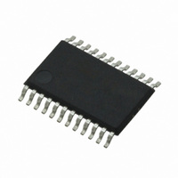
CS4270-DZZ Cirrus Logic Inc, CS4270-DZZ Datasheet - Page 28

CS4270-DZZ
Manufacturer Part Number
CS4270-DZZ
Description
IC CODEC 24BIT 105DB 24TSSOP
Manufacturer
Cirrus Logic Inc
Type
Stereo Audior
Specifications of CS4270-DZZ
Data Interface
Serial
Resolution (bits)
24 b
Number Of Adcs / Dacs
2 / 2
Sigma Delta
Yes
Dynamic Range, Adcs / Dacs (db) Typ
105 / 105
Voltage - Supply, Analog
3.1 V ~ 5.25 V
Voltage - Supply, Digital
3.1 V ~ 5.25 V
Operating Temperature
-40°C ~ 85°C
Mounting Type
Surface Mount
Package / Case
24-TSSOP
Audio Codec Type
Stereo
No. Of Adcs
1
No. Of Dacs
1
No. Of Input Channels
3
No. Of Output Channels
3
Adc / Dac Resolution
24bit
Sampling Rate
216kSPS
Ic Interface Type
I2C
Lead Free Status / RoHS Status
Lead free / RoHS Compliant
For Use With
598-1002 - BOARD EVAL FOR CS4270 CODEC
Lead Free Status / RoHS Status
Lead free / RoHS Compliant, Lead free / RoHS Compliant
Other names
598-1622
Available stocks
Company
Part Number
Manufacturer
Quantity
Price
Company:
Part Number:
CS4270-DZZ
Manufacturer:
CIRRUS
Quantity:
9
Company:
Part Number:
CS4270-DZZ
Manufacturer:
CIRRUS
Quantity:
62
28
5.4
5.4.1 Input Connections
Analog Connections
The analog modulator samples the input at 6.144 MHz.The digital filter will reject signals within the stop-
band of the filter. However, there is no rejection for input signals which are multiples of the input sampling
frequency (n
of the analog input network. The capacitor values chosen not only provide the appropriate filtering of noise
at the modulator sampling frequency, but also act as a charge source for the internal sampling circuits.
The use of capacitors which have a large voltage coefficient (such as general purpose ceramics) must be
avoided since these can degrade signal linearity.
Three parameters determine the values of resistors R1 and R2 as shown in
attenuation, and input impedance.
Source Impedance: Source impedance is defined as the impedance as seen from the ADC looking back
into the signal network. The ADC achieves optimal THD+N performance when source impedance is min-
imized and THD+N degrades for source impedance greater than 1 kΩ. See
Input
Analog
×
6.144 MHz), where n=0,1,2,... Refer to
Figure 16. A/D THD+N Performance vrs. Input Source Resistance
Figure 15. CS4270 Recommended Analog Input Network
R1
Table 6
R2
shows the design equation used to determine these values.
10 µF
Figure 15
220 pF
which shows the recommended topology
AINx
CS4270
Figure 15
Figure 16
source impedance,
and
17
CS4270
DS686PP1
below.


