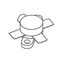
BLW96 NXP Semiconductors, BLW96 Datasheet - Page 11

BLW96
Manufacturer Part Number
BLW96
Description
NPN silicon planar epitaxial transistor intended for use in class-A,AB and B operated high power industrial and military transmitting equipment in the HF and VHF band
Manufacturer
NXP Semiconductors
Datasheet
1.BLW96.pdf
(14 pages)
Specifications of BLW96
Transistor Polarity
NPN
Number Of Elements
1
Collector-emitter Voltage
55V
Emitter-base Voltage
4V
Collector Current (dc) (max)
12A
Dc Current Gain (min)
15
Power Dissipation
340W
Frequency (max)
245MHz
Operating Temp Range
-65C to 200C
Operating Temperature Classification
Military
Mounting
Screw
Pin Count
4
Lead Free Status / Rohs Status
Compliant
Available stocks
Company
Part Number
Manufacturer
Quantity
Price
Company:
Part Number:
BLW96
Manufacturer:
WESTCODE
Quantity:
120
Part Number:
BLW96D
Manufacturer:
ASI
Quantity:
20 000
Philips Semiconductors
R.F. performance in s.s.b. class-A operation (linear power amplifier)
V
List of components:
Note
1. Stated intermodulation distortion figures are referred to the according level of either of the equal amplified tones.
August 1986
handbook, full pagewidth
C1 = C2 = 10 to 780 pF film dielectric trimmer
C3 = 220 nF polyester capacitor (100 V)
C4 = 100 F/4 V electrolytic capacitor
C5 = 2
C6 = 47 F/63 V electrolytic capacitor
C7 = C10 = 2
C8 = C9 = 10 to 150 pF air dielectric trimmer
L1 = 45 nH; 2 turns enamelled Cu wire (1,6 mm); int. dia. 8,0 mm; length 4,0 mm; leads 2
L2 = Ferroxcube wide-band h.f. choke, grade 3B (cat. no. 4312 020 36640)
L3 = 110 nH; 4 turns enamelled Cu wire (2,0 mm); int. dia. 10,0 mm; length 8,0 mm; leads 2
L4 = 210 nH; 5 turns enamelled Cu wire (2,0 mm); int. dia. 12,0 mm; length 10,0 mm; leads 2
R1 = 27
CE
HF/VHF power transistor
Relative to the according peak envelope powers these figures should be increased by 6 dB.
= 40 V; T
OUTPUT POWER
typ. 50 (P.E.P.)
330 nF polyester capacitors (100 V) in parallel
carbon resistor ( 5%; 0,5 W)
h
= 25 C; f
W
82 pF ceramic capacitors (500 V) in parallel
50
1
= 28,000 MHz; f
C1
V BB
typ. 19
2
Fig.18 Test circuit; s.s.b. class-A.
C2
dB
G
= 28,001 MHz
L1
p
L2
C3
C4
R1
11
T.U.T.
C5
C6
I
A
4
C
L3
L4
C7
V CC
typ. 40
C8
d
dB
3
C10
C9
(1)
MGP701
3 mm
2 mm
2 mm
Product specification
50
<
BLW96
d
dB
5
(1)
40


