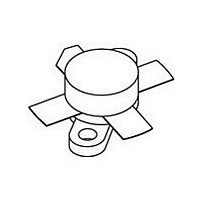
BLW96 NXP Semiconductors, BLW96 Datasheet - Page 6

BLW96
Manufacturer Part Number
BLW96
Description
NPN silicon planar epitaxial transistor intended for use in class-A,AB and B operated high power industrial and military transmitting equipment in the HF and VHF band
Manufacturer
NXP Semiconductors
Datasheet
1.BLW96.pdf
(14 pages)
Specifications of BLW96
Transistor Polarity
NPN
Number Of Elements
1
Collector-emitter Voltage
55V
Emitter-base Voltage
4V
Collector Current (dc) (max)
12A
Dc Current Gain (min)
15
Power Dissipation
340W
Frequency (max)
245MHz
Operating Temp Range
-65C to 200C
Operating Temperature Classification
Military
Mounting
Screw
Pin Count
4
Lead Free Status / Rohs Status
Compliant
Available stocks
Company
Part Number
Manufacturer
Quantity
Price
Company:
Part Number:
BLW96
Manufacturer:
WESTCODE
Quantity:
120
Part Number:
BLW96D
Manufacturer:
ASI
Quantity:
20 000
Philips Semiconductors
APPLICATION INFORMATION
R.F. performance in s.s.b. class-AB operation (linear power amplifier)
V
List of components:
Notes
1. Stated intermodulation distortion figures are referred to the according level of either of the equal amplified tones.
2. ATC means American Technical Ceramics.
August 1986
handbook, full pagewidth
C1 = C4 = C10 = C14 = 100 pF film dielectric trimmer
C2 = 27 pF ceramic capacitor (500 V)
C3 = 270 pF polysterene capacitor (630 V)
C5 = C7 = C8 = 220 nF multilayer ceramic chip capacitor
C6 = 27 pF multilayer ceramic chip capacitor (500 V; ATC
C9 = 47 F/63 V electrolytic capacitor
C11 = 2
C12 = 2
C13 = 43 pF multilayer ceramic chip capacitor (500 V; ATC
L1 = 88 nH; 3 turns Cu wire (1,0 mm); int. dia. 9,0 mm; length 6,1 mm; leads 2
L2 = Ferroxcube wide-band h.f. choke, grade 3B (cat. no. 4312 020 36640)
L3 = 150 nH; 5 turns Cu wire (2,0 mm); int. dia. 10,0 mm; length 18,7 mm; leads 2
L4 = 197 nH; 5 turns Cu wire (2,0 mm); int. dia. 12,0 mm; length 18,6 mm; leads 2
R1 = 0,66 ; parallel connection of 5
R2 = 27
CE
HF/VHF power transistor
Relative to the according peak envelope powers these figures should be increased by 6 dB.
= 50 V; T
OUTPUT POWER
50
25 to 200 (P.E.P.)
36 pF multilayer ceramic chip capacitors (500 V; ATC
43 pF multilayer ceramic chip capacitors (500 V; ATC
carbon resistor ( 5%; 0,5 W)
W
h
= 25 C; f
C2
C1
1
compensated bias
= 28,000 MHz; f
C3
temperature
(R i
dB
G
13,5
C4
p
0.1 )
L1
3,3
R1
2
Fig.8 Test circuit; s.s.b. class-AB.
= 28,001 MHz
L2
dt
metal film resistors (PR37;
at 200 W (P.E.P.)
40
(%)
C5
R2
(2)
T.U.T.
6
(2)
)
I
C
)
5,0
(A)
(2)
(2)
C9
C7
C8
) in parallel
) in parallel
C6
L4
L3
5%; 1,6 W each)
d
dB
C10
C11
3
C12
(1)
30
V CC
5 mm
5 mm
5 mm
C13
MGP691
d
C14
dB
5
(1)
30
Product specification
50
BLW96
I
C(ZS)
0,1
A


