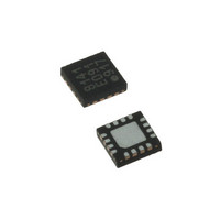
LDS8141-002-T2 IXYS, LDS8141-002-T2 Datasheet - Page 13

LDS8141-002-T2
Manufacturer Part Number
LDS8141-002-T2
Description
IC LED DRIVER WHIT BCKLGT 16WQFN
Manufacturer
IXYS
Series
LED-Sense™, Power-Lite™r
Type
Backlight, White LED (I²C Interface)r
Datasheet
1.LDS8141-002-T2.pdf
(22 pages)
Specifications of LDS8141-002-T2
Topology
High Side, Linear (LDO), PWM
Number Of Outputs
4
Internal Driver
Yes
Type - Primary
Backlight
Type - Secondary
White LED
Frequency
1.2MHz
Voltage - Supply
2.5 V ~ 5.5 V
Mounting Type
Surface Mount
Package / Case
16-WQFN, 16-miniQFN
Operating Temperature
-40°C ~ 85°C
Current - Output / Channel
32mA
Internal Switch(s)
Yes
Efficiency
80%
Lead Free Status / RoHS Status
Lead free / RoHS Compliant
Voltage - Output
-
Lead Free Status / Rohs Status
Details
Other names
LDS8141-002-T2-2
LDS8161/41
The de-rate table stored in the correction LUT is
referenced to the LED Tj. Register 49h can be used
to apply the Ta-Tj temperature offset between the
ambient and LED junction temperature. This can
effect a +/- shift of the de-rating curve in the
Temperature axis to reference the de-rating profile to
ambient, and/or set the start of de-rating to the
desired ambient temperature level to accommodate
different LEDs and current/power levels. The default
table will de-rate the current ~ - 9.2 dB (0.348x) from
its user set low temperature maximum level over
35ºC (from the start of the de-rate temperature). For
example, if the LED current is set to 30mA prior to
de-rating, and de-rating begins at 55ºC, at 85ºC the
current is de-rated to 0.348 x 30mA = 10.4mA.
Register 4Ah sets the LEDs shutdown junction
temperature per the T-codes provided in Table 7.
When this temperature is exceeded, all of the LED
current driver channels are disabled to insure no
damage to the LEDS. Additionally, an LED OT (over
temperature) status flag is set HIGH in Bit 7 of the
enable channel register 03h. If the flag is set the user
can re-enable the channels by re-writing to the
channel enable bits in register 03h, however the OT
flag will still remain HIGH, until the device is power
sequenced, reset, or placed in the shutdown mode.
If a Ta-Tj offset is used other than 00h (i.e. 0ºC) in
register, 49h, than the shutdown junction temperature
loaded in 4Ah should also include this offset. This
insures the LED shutdown is also properly referenced
to ambient level, Ta.
LED Current Setting
Current setting registers 00h – 02h should be
programmed using I
should be enabled using register 03h before LEDs
turn on.
The standard I
program I
LDS8161/41 should be addressed with slave address
chosen
addresses) followed by register address (00h, 01h, or
02h) and data that represents the code for the
desired LED current.
Code for LED current is determined as I
in hex format, i.e. 20 mA current code = 20/0.125 =
160 (dec) = A0h.
The maximum current setting is 31.875 mA. Since
the LDS8161/41 is a low drop-out LDO based linear
LED driver, when using maximum current levels,
users should
maximize operation with Li-ion batteries.
© 2009 IXYS Corp.
Characteristics subject to change without notice
LED
(see
current (see chapter “I
2
Table
C interface procedure is used to
select LEDs with V
2
C interface and desired LEDs
11
for
accessible
2
C INTERFACE”).
F
LED
< 3.3V to
/0.125 mA
slave
13
To turn LEDs ON/OFF register 03h should be
addressed with data that represents the desired
combination of LEDs turned ON/OFF (see Table 1);
i.e. if LEDC1, LEDC2, LEDA1, LEDA2 should be ON,
and LEDB1, LEDB2 should be OFF, binary code that
should be written into register 03h is 110011 (bin) =
33h.
The LDS8161/41 allows two ways for LED current
setting and dimming; analog (static) dimming using
the 8 bit current DACs, and dynamic dimming via the
integrated 12-bit digital PWM. Combining both
methods allows for total dimming capability of >
16,384:1
Analog dimming using the current setting DACs
discussed via registers 00h – 02h is referred to as the
static mode. Digital dimming using the internal PWM
generator changes the duty cycle per the value set in
register 05h and therefore adjusts the average LED
current. This is referred to as dynamic mode.
For dynamic mode, the LDS8161/41 integrates a
digital PWM generator that operates at a frequency of
~ 285 Hz. It operates in Logarithmic Mode. The PWM
generator
programmed with an 8-bit code to provide 256
internally mapped 12-bit logarithmic duty cycle steps
to adjust the dimming level
The advantage of PWM dimming is stable LED color
temperature / wavelength that is determined by the
maximum static mode LED current value set by
registers 00h – 02h. The integrated PWM generator
reduces the system requirement to provide a
continuous pulsed waveform.
To use the dynamic PWM mode for LED current
setting, the maximum I
current DAC registers 00h – 02h as described above
for static mode, and desired dimming / duty cycle can
be set by register 05h. The logarithmic operating
mode provides a dimming resolution of approximately
-0.17 dB per step with 0dB dimming (i.e. 100% duty
cycle) at the 256
(~ -80 dB dimming) at 00h.
LED-Sense
The LDS8161/41 integrates the IXYS LED-Sense
temperature measurement and high temperature
current de-rating algorithm to insure LED reliability
and operating lifetimes.
LED current is de-rated via reductions in PWM duty
cycle to meet LED vendor power dissipation vs. LED
junction temperature specifications.
User programmable de-rating adjustments are stored
in a correction LUT comprised of eight 8-bit registers
from 56h to 5Dh. Each register stores a 4-bit
TM
has
High Temperature Current De-rating
th
12-bit
step (i.e. FFh), and 0% duty cycle
LED
Doc. No. 8141/61_DS, Rev. N1.0
resolution
value should first be set by
and
can
be
TM


