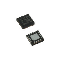
LDS8141-002-T2 IXYS, LDS8141-002-T2 Datasheet - Page 6

LDS8141-002-T2
Manufacturer Part Number
LDS8141-002-T2
Description
IC LED DRIVER WHIT BCKLGT 16WQFN
Manufacturer
IXYS
Series
LED-Sense™, Power-Lite™r
Type
Backlight, White LED (I²C Interface)r
Datasheet
1.LDS8141-002-T2.pdf
(22 pages)
Specifications of LDS8141-002-T2
Topology
High Side, Linear (LDO), PWM
Number Of Outputs
4
Internal Driver
Yes
Type - Primary
Backlight
Type - Secondary
White LED
Frequency
1.2MHz
Voltage - Supply
2.5 V ~ 5.5 V
Mounting Type
Surface Mount
Package / Case
16-WQFN, 16-miniQFN
Operating Temperature
-40°C ~ 85°C
Current - Output / Channel
32mA
Internal Switch(s)
Yes
Efficiency
80%
Lead Free Status / RoHS Status
Lead free / RoHS Compliant
Voltage - Output
-
Lead Free Status / Rohs Status
Details
Other names
LDS8141-002-T2-2
LDS8161/41
LDS8161 / 41 REGISTERS DEFINITION AND PROGRAMMING
Note: Unlisted register addresses are for factory use only; For proper operation write only to registers defined.
© 2009 IXYS Corp.
Characteristics subject to change without notice
ADDRESS
56h – 5Dh
1Ch
1Dh
00h
01h
02h
03h
05h
19h
1Eh
1Fh
49h
4Ah
4Bh
DESCRIPTION
Bank A Current setting
Bank B Current setting
Bank C Current setting
(8161 only; Not for 8141)
Channel Enable
(No Bits 5, 4 for C2 and
C1 respectively for 8141)
Bank A, B, C PWM Duty
Cycle
LED Diagnostics Test
LED Faults Status
( shorted to GND)
LED Faults Status
(shorted to V
Configuration register
Software reset, Standby
Ta-Tj Temperature Offset
LED Shutdown
Temperature
2-x Table enable and
breakpoint (T-code)
Temp De-rating LUT
25C to 100C
(one 5C step every
nibble)
Δ PWM code1[7:4],
Δ PWM code0[3:0] –
Δ PWM code13[7:4],
Δ PWM code12[3:0]
IN
/open)
BITS
8
8
8
6
8
8
5
5
8
8
8
5
6
8
NOTES
Reg00h – Reg02h data code = (I
converted into hex format
Bits 5:0 = 1 enables LEDs C2, C1, B2, B1, A2, A1
respectively (See
Table 1). Both LEDs from one bank should be disabled to
minimize power consumption.
Log Mode:
~ – 0.17dB dimming per LSB for currents > 300 µA; Refer to
8 to 12 bit conversion curve (Figure 3 and Table 10) for
resolution in range 0 – 300 µA
Data Code 00h = 0% Duty Cycle, FFh = 100% Duty Cycle
Example: 50% brightness reduction ( – 6dB) requires: 255 –
(– 6 dB / – 0.17 dB) = 255 – 35 = 220 (decimal) = DCh steps
See Table 2; Bit 5 = 1 sets user-initiated LED short/open
diagnostic
Bits from bit 5 to bit 0 represent LED status for LEDC2 –
LEDA1 respectively. Bit = 1 represents LED shorted to GND
Bits from bit 5 to bit 0 represent LED status for LEDC2 –
LEDA1 respectively. Bit = 1 represents LED shorted to
V
See Table 3
See Table 4
Since junction temperature is measured, the values loaded
here allow an offset to account for Tj – Ta gradient.
This allows de-rate tables to be referenced to Ta levels.
Two 4 bit offsets value for the LED and the Si Diode;
Bit [7:4] = Tj-Ta offset for the LEDs
Bit [3:0] = Tj-Ta offset for the Si diode.
Typically should set both offsets to be equal.
Defines T-code, at which LED current shuts down per LED
vendor de-rating specification (see Table 5); Factory default
value = 11100 (bin) = 1Ch represents 105
Bit 5 = 1 – enable 2-x scale LUT Δ PWM code correction (de-
rating) starting at the breakpoint set by T-code (bits 4:0)
Bit 5 = 0 – 1-x scale (default) for entire temperature range
Bit [4:0] defines T-code, where temperature de-rating starts,
or where 2-x scaling begins (see Table 5)
Two LUT words per I
Each word contains two 4-bit numbers repres enting of Δ PWM
codes. See
Table 6 and Appendix 1 for LUT programming.
Factory default setting is Logarithmic Mode table for WLED
LED (Nichia NSSW020BT WLED).
Default table could be used for WLED de-rating.
De-Rating starts at 55ºC junction.
See Table 5 & 6
IN
/open
6
2
C address.
LED
Doc. No. 8141/61_DS, Rev. N1.0
/ 0.125 mA) (decimal)
0
C Tj


