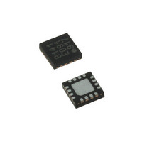
LDS8141-002-T2 IXYS, LDS8141-002-T2 Datasheet - Page 7

LDS8141-002-T2
Manufacturer Part Number
LDS8141-002-T2
Description
IC LED DRIVER WHIT BCKLGT 16WQFN
Manufacturer
IXYS
Series
LED-Sense™, Power-Lite™r
Type
Backlight, White LED (I²C Interface)r
Datasheet
1.LDS8141-002-T2.pdf
(22 pages)
Specifications of LDS8141-002-T2
Topology
High Side, Linear (LDO), PWM
Number Of Outputs
4
Internal Driver
Yes
Type - Primary
Backlight
Type - Secondary
White LED
Frequency
1.2MHz
Voltage - Supply
2.5 V ~ 5.5 V
Mounting Type
Surface Mount
Package / Case
16-WQFN, 16-miniQFN
Operating Temperature
-40°C ~ 85°C
Current - Output / Channel
32mA
Internal Switch(s)
Yes
Efficiency
80%
Lead Free Status / RoHS Status
Lead free / RoHS Compliant
Voltage - Output
-
Lead Free Status / Rohs Status
Details
Other names
LDS8141-002-T2-2
LDS8161/41
Table 1
Table 2
Note: *) Value by default
© 2009 IXYS Corp.
Characteristics subject to change without notice
Register
Address
Register
Address
(8161)
(8141)
03h
19h
A0h
A2h
D4h
D6h
C0h
Factory
Same
Bit 7
LED
Flag
Bit 7
Only
OT
Silicon diode dV
LED dV
Silicon diode η [7:0]
Silicon diode R
[7:0]
LED Rs offset [7:0]
0*
Bit 6
F
N/A
N/A
Factory
/dT [7:0]
Bit 6
Only
0*
s
Enable C2
F
offset
/dT [7:0]
Diagnostics
Bit 5
N/A
Request
Bit 5
0*
Enable C1
8
8
8
8
8
Slow Ramp
Bypass = 1
Bit 4
N/A
Digital Test Modes Register
Channel Enable Register
Bit 4
Silicon diode V
Factory recommended loaded value is 36h = -1.71 mV/°C =
where bits from bit 7 to bit 5 represent integer part
[1(decimal) = 001 (bin)], and bits from bit 4 to bit 0 – fractional
part [0.710 / 0.03125 = 22 (decimal) = 10110 (bin)]
User-loaded V
used at Banks A, B, C respectively.
Negative tracking is assumed with temperature;
Bits from bit 7 to bit 5 represent integer part and
bits from bit 4 to bit 0 - fractional part of the coefficient
Example: Temperature coefficient = -2.26 mV/
Bit 7 – bit 6 = 2 (decimal) = 010 (bin), and
Bit 4 – bit 0 = INT{0.26 / 0.03125} = 8 (decimal) = 01000 (bin)
User loads 010 01000 (bin) = 48h = -2.25 (closest setting)
Silicon diode η (eta, or non-ideality factor):
Factory recommended loaded value is default is 1.00 =
01000000(bin) = 40h
Bits from bit 7 to bit 5 represent integer part and
bits from bit 4 to bit 0 - fractional part (resolution = 0.015625
per LSB)
Example: η = 1.00;
Bit 7 – bit 6 = 1 (decimal) = 01 (bin), and
Bit 5 – bit 0 = INT{0.00 / 0.015625} = 0 (dec) = 000000 (bin)
User loads 01 000000 = 40h = 1.00
Silicon diode series resistance offset
Factory recommended loaded value = 04h = ~ 68 ohms
Formula (decimal) = 8192 x [(68 ohms x 8 x 10
LED Rs offset (user-loaded) for Banks A, B, and C LEDs
Typically LED Rs = 5 – 30 Ω
User loads per LED used. (1/slope of high current region of
LED I-V characteristic).
Formula (decimal) = 8192 x [(Rs Ωx 8 x 10
0*
001 10110 (bin),
7
Enable B2
Same
Normal = 0*
Bit 3
Fast PWM
adjust =1
Bit 3
F
F
temperature coefficient @ 1mA for LEDs
temperature coefficient (K factor) :
Enable B1
Same
Bit 2
Factory
Bit 2
Only
0*
Doc. No. 8141/61_DS, Rev. N1.0
Post ADC Filter
Enable A2
Filter Off=0*
Same
Enable =1
Bit 1
Bit 1
- 4
A) / 1.14V]
0
- 6
C;
A)/1.14 V]
Enable A1
Same
Bit 0
Factory
Bit 0
Only
0*


