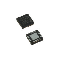
LDS8141-002-T2 IXYS, LDS8141-002-T2 Datasheet - Page 3

LDS8141-002-T2
Manufacturer Part Number
LDS8141-002-T2
Description
IC LED DRIVER WHIT BCKLGT 16WQFN
Manufacturer
IXYS
Series
LED-Sense™, Power-Lite™r
Type
Backlight, White LED (I²C Interface)r
Datasheet
1.LDS8141-002-T2.pdf
(22 pages)
Specifications of LDS8141-002-T2
Topology
High Side, Linear (LDO), PWM
Number Of Outputs
4
Internal Driver
Yes
Type - Primary
Backlight
Type - Secondary
White LED
Frequency
1.2MHz
Voltage - Supply
2.5 V ~ 5.5 V
Mounting Type
Surface Mount
Package / Case
16-WQFN, 16-miniQFN
Operating Temperature
-40°C ~ 85°C
Current - Output / Channel
32mA
Internal Switch(s)
Yes
Efficiency
80%
Lead Free Status / RoHS Status
Lead free / RoHS Compliant
Voltage - Output
-
Lead Free Status / Rohs Status
Details
Other names
LDS8141-002-T2-2
LDS8161/41
RECOMMENDED OPERATING CONDITIONS
Typical application circuit with external components is shown on page 1.
ELECTRICAL OPERATING CHARACTERISTICS
Note:
© 2009 IXYS Corp.
Characteristics subject to change without notice
(Over recommended operating conditions unless specified otherwise) V
Name
LEDx Current DAC Resolution/step
V
I
Total Output Current I
Junction Temperature Range
LEDx Channel Current DAC Range
# of LEDx Current steps (linear steps)
Quiescent Current
Shutdown Current
LED Current Accuracy
LED Channel Matching
Line Regulation
Load Regulation
Dropout Voltage
PWM Frequency
# of PWM duty cycle steps
Minimum PWM On Time
PWM resolution
PWM Step Size
of PWM Steps for current de-rating
De-rating Temperature Adjust Steps
Programmable De-rating Start
Temperature (Tj) Range (typical)
Programmable LED Shutdown
Temperature(Tj) Range (typical)
Input Current Limit
Thermal Shutdown
Thermal Hysteresis
Wake-up/Shutdown Delay Time from EN
Raising/Falling Edge
Output short circuit Threshold
EN Pin
LED
IN
per LED pin
1. Vdx = Vin – V
2. Vdx = Vin – V
3. Minimum LED forward voltage, which will be interpreted as “LED SHORT” condition
Input current
Logic Level
1
2
Parameter
F
F
,
, at which I
LOAD
EN = V
6/4 Channels at 100%
DC PWMs and Temp
De-Rating Active
High
Low
ILED
IN
3
decreases by 10% from set value
Conditions
Standby (no I
I
I
V
5 mA ≤I
(I
2.7 V ≤V
0.2 V < Vdx < 1.2 V
1 mA ≤I
Log Mode steps
Log Mode
Log Mode
1-x Scale Mode
2-x Scale Mode
Active mode, EN = V
Normal Standby
Active Mode or Normal
Standby Mode
Soft ramp disabled
Soft ramp enabled
I
LOAD
LOAD
LED
EN
LED
= 0V
= 20 mA
- I
= 120 mA/ 80 mA
= 60 mA / 40 mA
LEDAVG
LED
LED
IN
3
-40 to +125
0 – 31.875
2.5 to 5.5
≤4.2 V
IN
≤30 mA
Rating
191.25
≤30 mA
2
) / I
= 3.6V, C
C clock)
LEDAVG
IN
IN
= 1 µF, EN = High, T
Min
-14
1.2
30
80
-7
-1
0
Unit
mA
mA
°C
V
0.45/0.35 0.35
0.6/0.45
0.125
±1.5
±1.5
13.7
0.17
0.14
Typ
256
125
0.5
285
256
105
450
150
250
50
12
55
20
10
2
1
5
5
AMB
Doc. No. 8141/61_DS, Rev. N1.0
= 25°C
31.875
Max
120
0.4
75
80
1
0
0
1
Steps/5
Units
steps
PWM
%/V
%/V
mA
mA
mA
mA
mV
bits
mA
µA
µA
Hz
dB
µA
ms
ms
µs
0
0
0
°C
%
%
V
V
C
C
C
0
C


